TPA6120A2 - is a cfa specialty,
i think i am going to play with this one a bit, they have a complete ref design available, i am looking over the gerber data now. a nice 4-layer design.
High Fidelity Audio Headphone Playback Reference Design for Portable and Smartphone Applications - TIDA-00385 - TI Tool Folder
i think i am going to play with this one a bit, they have a complete ref design available, i am looking over the gerber data now. a nice 4-layer design.
High Fidelity Audio Headphone Playback Reference Design for Portable and Smartphone Applications - TIDA-00385 - TI Tool Folder
Dan, I think you're generalizing here.Pro Tools has taken a very long time to come to the party, Samplitude has incorporated this signal flow since day one.
For some obscure reason, the technically and sonically inferior prior versions of PT have been the defacto standard in pro audio world....those who are more critical have always advocated Samplitude.
Samplitude, being 'native' software, came way later than PT. PT started on a 68k Mac with all processing offloaded to dedicated DSP cards (Moto 56k). On PC side there was 486 at that time. That's not much of a resources to run any serious processing in real time 😉
Also, it was evidenced that some early versions of Samplitude were 'broken'.
(I have tests from 1999 on my computer that show version 5.10 of Samplitude behaving rather strangely).
square wave test for 2nd
But since a device with a simple smooth nonlinear response that produces 2nd will also show a d.c. shift, even excited by a sinusoid, looking for either 2nd or the d.c. shift (or both) can be instructive. If there is one or more highpass filters in the chain, of course the d.c. will be blocked, but there should still be some 2nd.
Slightly off topic: it can be conjectured that the fondness some have for second harmonic distortion might be associated, to some extent, with the small transient that would manifest as a d.c. shift if the low frequency response were unlimited. Of course the change in timbre is the accepted effect, and is certainly present. Among the comments from listeners who seem to prefer or at least not mind 2nd, I hear that somehow the music is more "alive", beyond just sounding a little richer or brighter.
Since asymmetrical slewing will produce a d.c. offset in a d.c.-coupled signal chain, a fast rise-fall time symmetrical square wave source can be used to identify such limitations. For a buffer amp to be used for a very old switching system, I constructed such a source. However I didn't use it to look for second, just as a tool to eliminate the signal-induced d.c. offset in the device under test.One thing that caught me in this paper is the use of a square wave test signal and then looking for even harmonics in the output signal. That seems like a interesting test - has anyone here ever done that or know of a reference where it has been done?
Jan
But since a device with a simple smooth nonlinear response that produces 2nd will also show a d.c. shift, even excited by a sinusoid, looking for either 2nd or the d.c. shift (or both) can be instructive. If there is one or more highpass filters in the chain, of course the d.c. will be blocked, but there should still be some 2nd.
Slightly off topic: it can be conjectured that the fondness some have for second harmonic distortion might be associated, to some extent, with the small transient that would manifest as a d.c. shift if the low frequency response were unlimited. Of course the change in timbre is the accepted effect, and is certainly present. Among the comments from listeners who seem to prefer or at least not mind 2nd, I hear that somehow the music is more "alive", beyond just sounding a little richer or brighter.
Is it only asymmetrical slewing that can cause 2nds from a square wave?
Of course it is very similar to a DIM30 test, but I have never read that one uses a DIM30 to look for 2nds, rather for IM poducts.
Anyway, it doesn't sound like an easy task to generate a spectrally pure square wave to begin with, which might be a reason why it didn't make it as a standard test.
Jan
On the contrary: the output of a fast flip-flop, fed by a reasonably clean and stable clock and buffered by a CMOS-like OP stage is very close to perfection, with very little effort or investment.Anyway, it doesn't sound like an easy task to generate a spectrally pure square wave to begin with
In practice, that would mean a crystal oscillator, a 74AC74 and a 74AC540.
For audio work, you don't need anything more perfect than that.
Two points: First, keep the short between the resistors on the top portion of the schematic. Thanks Patrick for fixing it for me. It is always uncomfortable to have all these typos.
Second, the TIM30 test is an extended version of the Holman test. I pushed to use 30KHz, because Holman first used it. 20KHz was also considered, but 30KHz made more sense. The TIM30 test will give you BOTH 2nd and 3'rd, or even or odd both. This makes it more inclusive. Pass TIM30 and you are doing darn well.
Second, the TIM30 test is an extended version of the Holman test. I pushed to use 30KHz, because Holman first used it. 20KHz was also considered, but 30KHz made more sense. The TIM30 test will give you BOTH 2nd and 3'rd, or even or odd both. This makes it more inclusive. Pass TIM30 and you are doing darn well.
Suppose the device-under-test's nonlinearity is a greatly simplified (and nonphysical) one, in which the gain for negative signals is different from that for positive, but a constant for each. Suppose however that the bandwidth of the DUT is unlimited at both extremes of frequency. Then a zero-d.c. symmetrical square wave input will produce a level-shifted output, but will still be a 50% duty cycle waveform, hence will contain no even-order harmonics.Is it only asymmetrical slewing that can cause 2nds from a square wave?
Of course it is very similar to a DIM30 test, but I have never read that one uses a DIM30 to look for 2nds, rather for IM poducts.
Anyway, it doesn't sound like an easy task to generate a spectrally pure square wave to begin with, which might be a reason why it didn't make it as a standard test.
Jan
Any real square wave will have finite rise and fall times. If the generator is designed to make them closely equal, and the positive and negative periods are equal, for which is pretty easy to do a decent approximation by clocking a flip-flop [EDIT: see for example Elvee's post above] whose output then controls the final generator output state, an averaging filter should settle to 0 volts d.c. There will be some small residual asymmetry if the flip-flop has a different propagation delay for a given transition. And there are other ways to generate the signal, but the clocked FF is pretty easy.
Another behavior of the DUT that may be exposed, that is not asymmetrical slewing, is signal-induced self-heating shifts. Of course the generator itself has to have stable flat tops.
The box I built at the time has +/- 20V swings, runs at 20kHz and has 20ns rise and fall times. I've misplaced the schematic. It could certainly be improved but it was useful for the task. It used some UHF medium-power transistors and had various clamping diodes to prevent saturation.
Last edited:
many function generators (HP, Wavetek etc) can be used just by selecting the SQ wave output. Everyone has a function generator as part of their basic test equipment. Or they should. Some have a variable on-off ratio or duty cycle to simulate a pulse.
If you only have a sine wave generator, you can square it up and then send to an edge triggered flip-flop.
THx-RNMarsh
If you only have a sine wave generator, you can square it up and then send to an edge triggered flip-flop.
THx-RNMarsh
Last edited:
I never measured-it. But each time i was○able to replace original OPAs by CFAs, there, the improvement was obvious, and sound back to life again.
Of course. Who needs measurements when "the improvement was obvious and sound back to life again"? Even you wife in the kitchen noticed the obvious improvement, isn't it?
Expectation bias is for the non believers only. Not to mention that op amp rolling is in general (and for CFAs in particular), an as bad as you can get engineering practice.
I believe in what my ears find. Today, I put the Marantz 10 tube tuner back in,(all fixed) and WOW! Of course, that was only in comparison to the Sony digitally based tuner that I have used for several years, now. However, the Sony is good enough for the news, etc. so I will keep in mostly.
Waly, you are not doing anybody any favors by badmouthing the way we listen. Some of us trust that we can put aside our biases. Usually, we are pros with a lot of ACTUAL live vs reproduction experience.
On the contrary: the output of a fast flip-flop, fed by a reasonably clean and stable clock and buffered by a CMOS-like OP stage is very close to perfection, with very little effort or investment.
In practice, that would mean a crystal oscillator, a 74AC74 and a 74AC540.
For audio work, you don't need anything more perfect than that.
Can you guarantee that's exactly 50.000001 % duty cycle?
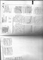
For completeness: This is the part (e110) that we used for the differential front end of the JC-2 phono stage. We operated each device at about 15ma for lowest noise. Earlier, before 1974, it was thought that this device was noisier than the noise curve with frequency shows here, but it really was like the curve shown here. Unfortunately, a few years later, about 1976, they changed the processing of the part (according to Ed Oxner) who then worked at Siliconix, and they got noisy again. This was unfortunate, and we had to wait until 1978 to get the first Toshiba parts in to improve the situation, and I have been using the Toshiba's or their equivalent, ever since. Even Toshiba, screwed up in 1990, and I had to reject a number of low noise devices from them. They got better, once again after 1991.
There is no guarantee that a 'low noise' part will continually meet its specs, unless the manufacturer stays with the same process. This is why I was concerned, years ago, when Scott Wurcer introduced the Phillips part, originally. There was not even a noise spec in the audio range on the part. They could have shipped just about anything! Fortunately, Phillips has shipped a very good part, but one must always be on guard (in production) that changes could be made by the factory, and the usefulness of the product lost.
There is no guarantee that a 'low noise' part will continually meet its specs, unless the manufacturer stays with the same process. This is why I was concerned, years ago, when Scott Wurcer introduced the Phillips part, originally. There was not even a noise spec in the audio range on the part. They could have shipped just about anything! Fortunately, Phillips has shipped a very good part, but one must always be on guard (in production) that changes could be made by the factory, and the usefulness of the product lost.
Attachments
If the output is centered at d.c. zero, a simple passive lowpass filter should allow a good d.c. voltmeter to assess the asymmetries.Can you guarantee that's exactly 50.000001 % duty cycle?
It's instructive to use a simulator (or crank out the maths) to see how much a differing positive versus negative slew rate generates how much d.c. offset and even-order harmonics.
The technique recommended by Elvee is likely to be a lot better than a commercial function generator, although I don't know how well HP/Agilent/Keysight does---they could be very good.
I just looked at a generic cheap function gen I use for government work and it has a significant d.c. offset, probably more due to the difference in the positive voltage magnitude versus the negative. In both cases the variable duty cycle control was set to cal (square wave) and the d.c. offset control was off. But the way in which the waveforms are generated allows for a number of errors. It's typically an integrator in a feedback loop with a comparator, which generates triangle waves at the integrator output and ~square waves at the comparator output. Then there is an output amplifier with its own additional aberrations.
I should go back and use my 2236 counter-timer to tell what the positive and negative durations actually are, so as to separate the offset issues from the timing issues.
EDIT: for a 19.85kHz nominal square wave, the pulse durations are 25.059us and 25.304us. For a 9V p-p output the d.c. offset is -275mV. It appears that this is mostly a real offset and only slightly due to the small timing asymmetry. Switching the scope from d.c. to a.c coupling and watching the displayed waveform reinforces this conclusion, but I can now determine the relative contributions. In any event, for a number of systems to be measured this would be enough to see gross DUT asymmetries. Oh, the rise and fall times appear identical at the scope and are about 100ns.
Last edited:
You can easily make your calculations based on your component choice: it depends on the skew of the F-F outputs and the difference between H-L and L-H transitions and delays of the buffer.Can you guarantee that's exactly 50.000001 % duty cycle?
Let's say you use AC logic, raw (no tuning or compensation), that could amount to 500ps + 1.5ns, 2ns total for a period of 1ms if you work at 1Khz, that would be 50.0002% d. This is an almost worst case, unadjusted, for quasi-obsolete logic.
I'll let you compute yourself the H2 content of such a waveform. If it isn't satisfactory enough, you can use faster logic, compensate it, and even use additional closed-loop tricks to gain a 1K factor if you think you really need it
You can easily make your calculations based on your component choice: it depends on the skew of the F-F outputs and the difference between H-L and L-H transitions and delays of the buffer.
Let's say you use AC logic, raw (no tuning or compensation), that could amount to 500ps + 1.5ns, 2ns total for a period of 1ms if you work at 1Khz, that would be 50.0002% d. This is an almost worst case, unadjusted, for quasi-obsolete logic.
I'll let you compute yourself the H2 content of such a waveform. If it isn't satisfactory enough, you can use faster logic, compensate it, and even use additional closed-loop tricks to gain a 1K factor if you think you really need it
And there are parts like this: http://www.micrel.com/_PDF/HBW/sy10ep31v.pdf
I need to revisit my experiments with dithering depth and spectral types, but as I recall, white noise dithering is readily audible, as are other flavours including the likes of Panasonic MASH and Sony SBM, amongst others.
Dan.
Don't mistake noise shaped sigma delta converters with simple dither.
Yes. Better to clip cleanly at line level, than hit the power amp hard and then complain that the output stage doesn't clip cleanly---IMO.
I agree.
You can have a look on this 1980 patent too
Distortion free power limiting and clipping prevention circuit
George
- Status
- Not open for further replies.
- Home
- Member Areas
- The Lounge
- John Curl's Blowtorch preamplifier part II