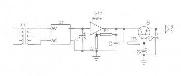
I know that many of you are virtually experts in power supply design, but I would like to go back and explain a few details for everyone else. What I consider most important is not the 'engineering' but the 'covering the bases' for a successful audio supply. Let's look again at my original simplified schematic:
Zener choice -
I use the zero TempCo for zener most of the time..... 4.7v. Its a good compromise number.... above, in avalance mode, the noise increases, as already said. The lowest noise is under 4.7v.... the 3.3 or 3.6v is near minimum noise.
However, in avalanche mode the TC is positive and below 4.7v it is negative TC. Depending on the circuit used, the TC can offset a transistors TC. And, a diode in series with a pos TC can make it a zero TC. A 3.6v has a neg TC of -2mv/degree. A 5.6v has a pos TC of +2mv/degree.... add a series diode (6.2v) for zero Tc and close to lowest Z zener.
But there is also the fact that to best regulate, the zener dynamic Z needs to be low. The lowest Z would be from about 7 volt zener (6.8 - 7.2). And, the zener must be operated well beyond its knee or zener break point.... higher currents thru the zener will lower the z and thus improve regulation; 20mA works better than 1 or 5ma.
THx-RNMarsh
Last edited:
I know that many of you are virtually experts in power supply design, but I would like to go back and explain a few details for everyone else. What I consider most important is not the 'engineering' but the 'covering the bases' for a successful audio supply. Let's look again at my original simplified schematic:
This one?
Attachments
Here are my thoughts on Curl's PSU:
Noise: The LM317 is noisy but most of that is filtered out by the C-multiplier. The noise of the C-multiplier approaches the lowest you can expect without rapidly inflating parts count. Low-frequency noise can still be significant unless C4 is made very large.
PSRR: The LM317 provides basic PSRR and constant voltage functionality. At AC, the C-multiplier will usually have much better PSRR than the LM317 at RF, and will have no more PSRR than the LM317 in the audio and ultrasonic range. In combination a very wide spectrum of noise has been effectively filtered out. Input transients can still cause the LM317 to act up, and if so, then better PSRR will be achieved by putting the C-multiplier before the LM317. The C-multiplier will protect the LM317 from the input transients which overload it's feedback loop and cause it to generate noise and allow noise through.
Output impedance: The C-multiplier will have the same output impedance as a diode with the same forward current. It will be much larger than the LM317, so if output impedance is very important, then having the C-multiplier after the LM317 can be a disadvantage. At the same time the enormous output inductance of the LM317 resonates with lytics and causes noise peaking in the audio or ultrasonic bands. The C-multiplier does not have this problem and it's relatively high output resistance tends to have a dampening effect on any resonances on the rails.
Last edited:
Here is a practical implemetation of the concept. The layout is very important - you need to see the PSU and the amplifer stages as a system.
Each of the gain blocks attached to this PSU runs in class A.
There are only low order harmonics on the supply rails
Each gain stage is decoupled from the supply rail with a 22 Ohm and 100uF cap (on both + and - rails). This heavy 'damping' means you done get the resonance problems that Kendall Castor-Perry talks about. The local decoupling around each opamp keeps any HF currents (and they are very small because everying is in class A) off the supply rails as well.
Secondaries have an RC network to deal with diode turn off - I used Morgan Jones generic 1nF+1k recomendation - I have not gotton around to actually doing a test to determine the exact values.
Running the stages in class A means the high OP impedance of the cap x is no longer a problem either.
Separate decouple ground from signal ground.
Attachments
Last edited:
That is a good summary, keantoken. The relatively high output impedance of the follower can be made less important by paralleling cap multipliers for each gain block, rather than using a single cap multiplier. In fact, the cap multiplier can be part of each individual gain block, so that it buffers the audio gain block from any outside rail pickup.
No comment, John, about the idea to set the regulation on one wire of each PSU and cap multiplier on the other side, to provide isolation between rectifiers and common ground ?
Hello John.That is a good summary, keantoken. The relatively high output impedance of the follower can be made less important by paralleling cap multipliers for each gain block, rather than using a single cap multiplier. In fact, the cap multiplier can be part of each individual gain block, so that it buffers the audio gain block from any outside rail pickup.
Is there a reason that you do not decouple the LM317 Adj pin ?.
Dan.
Interesting link that seems to show low volt zeners as the quietest!
http://ams.aeroflex.com/metelicsHRC/pdfiles/1N4099-1N4135_1N4614-4627.pdf
Wrinkle
http://ams.aeroflex.com/metelicsHRC/pdfiles/1N4099-1N4135_1N4614-4627.pdf
Wrinkle
LM317 is noisy if you don't follow Erroll Dietz's recommendations- heavy bypassing of adjust pin and output and pre-loading it to deliver current. Do that and it's reasonably quiet. If that's still too noisy, you might want to reconsider your signal circuit design- any circuit that has no PSR is questionable.
All that matters is what the overall circuit puts out. 40dB of noise reduction in the reg and 40dB of PSR is equivalent (and MUCH easier) than 80dB of noise reduction in the reg and no PSR.
I should mention that there's an easy way to get under 1.5nV/rt Hz noise across the audio band along with better than 80dB of line rejection...
any circuit that has no PSR is questionable.
All that matters is what the overall circuit puts out. 40dB of noise reduction in the reg and 40dB of PSR is equivalent (and MUCH easier) than 80dB of noise reduction in the reg and no PSR.
That's it. Not about "audiophile" designs that have no PSR and request unlimited capacitor banks or cascades of capacitance multipliers. Also note that the promoters will NEVER show any measurement of the noise bottom.
Bonsai, how much current is it good for - just wondering?
Circa 20 W in total for the whole preamp.
It could easily deliver more, but the cap x transistors need to be rated for higher current - 15032/33 for example.
"I should mention that there's an easy way to get under 1.5nV/rt Hz noise across the audio band along with better than 80dB of line rejection..."
I'm all ears.
Batteries don't count.
I'm all ears.
Batteries don't count.
Bonsai, I should qualify that- those numbers relate to a preamp supply of 17V or so. Higher voltages will mean slightly higher noise: 3dB more for 35V, for example.
Still all ears?
Still all ears?
"I should mention that there's an easy way to get under 1.5nV/rt Hz noise across the audio band along with better than 80dB of line rejection..."
I'm all ears.
Batteries don't count.
Split voltage and current.
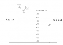
Just filter the heck out of a reference voltage by a very large R - very large C filter, think 100-rds of Ks over 100-rds of uF. You wind up with basically the capacitor noise, but with almost no current producing capacity. Feed this filtered voltage reference into a low noise opamp or opamp/buffer combination to produce the desired current capability and presto. You have the best of both worlds, extremely low noise, as well as minimal Zout.
Edit: hang the opamp/buffer behind an R (10-100Ohm) C (large) filtered supply, an old Philips trick. You lose quite a bit of voltage, but that is 2nd law.
Last edited:
Yes - still all ears 🙂 and always ready to learn a new trick or two!
I'll hazard some guesses
You can use an opamp to supply another opamp. So run the + supply using 1 opamp running between 0V and the unreg V+ and use the same approach on the - supply. Use a well filtered Zener for Vref.
A good opamp will get you to 120 dB PSRR at low to mid f, and 80 dB at 20 kHz.
The signal amplifying opamp also has outstanding PSRR, so when you look at the overall system PSRR, it's theoretically exceedingly good - certainly well above 80 dB across the audio band, and it can be very quiet as well.
When I talk about good opamps, I mean Scotties and LME4xxx types.
Still another option is to simply bootstrap the supplies ref the output.
Etc
Etc
- Status
- Not open for further replies.
- Home
- Member Areas
- The Lounge
- John Curl's Blowtorch preamplifier part II