Sigh. I'm at the wrong computer now. I think somebody here can provide the links to Cyril's papers.. otherwise, it'll have to wait until I go to the other later.Links, pictures?
Any sane person should be.I am skeptical of the audibility also.
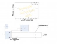
It can. Either use a low milliohm zero bdot cvr at the amp out, and measure the zero crossing delay between the voltage across the line and the current drawn by the load at the other. The only time difference in current from one end of the line to the other will be one transit delay, or about 20 nSec. I recommend measureing the load current at the amp because doing so at the load raises "heck" with the scope grounding.The waveforms are clear why can't a direct measurement be done?
The other way is to use a modified rf bridge. Yuk.
edit: attached is the test setup. Frequency is arbitrary, I believe Cyril used 1Khz as well.
The resistor is extremely important, as it's self inductance will be very significant compared to the IR drop at 100 milliohm.
Also, use a really good resistor at the load.
Some may remember, this is not the first time I've posted this.
Yes.Was your plot a voltage step at one end and the voltage at the other end?
No matter what the amp does, the line will initially charge voltage and current at the line's impedance. One transit delay after the amp does something, the load only sees what passes through the mismatch interface via the transmission coefficient.
The difficult thing with audio is the wavelengths for audio signals are so slow, that we can't see directly the reflections and the composite effect the line to load mismatch has on the current through the load.
jn
Attachments
Last edited:
The difficult thing with audio is the wavelengths for audio signals are so slow, that we can't see directly the reflections and the composite effect the line to load mismatch has on the current through the load.
jn
Thanks, a couple of experiments to try (you do mean long not slow?). One quick question is that plot the absolute value of phase? Dimitri is sending Mr. Bateman's papers.
Thanks, a couple of experiments to try (you do mean long not slow?). One quick question is that plot the absolute value of phase? Dimitri is sending Mr. Bateman's papers.
Yes, I meant long. The rate of change of the audio voltages is very slow in comparison to the wire lengths we discuss, so it is impossible to see how the cable fills up with energy..
The primary purpose of the plot is to convey the cusp which occurs when line and load are matched. Below the cusp is where inductance dominates, that is where my settling time graph details. Above the cusp, capacitive storage dominates. That is also the region where I mention hot amps and phase margin concerns.
It's moreso a delay plot, but at a single frequency the distinction would be moot. Delay is somewhat easier to understand conceptually, and I'm keeping it simple..
Cyril's papers....Look for the scope photo, it shows the sent and reflected wave, and if IIRC, it points out the delay.
ps...you need a low inductance cvr?
jn
JN,
I cant sum two speakers on one channel as you suggested, Z-min would be .5 ohm, the amplifier sonics changes when below 1 ohm, it's why i made the load 1 ohm, 1-1.5 gave me best sonics, 1ohm had best drive, below this the tonal balance on all the amps i have tried changes, kills the sonics.
What about playing in mono , i have done this and observed what you have suggested with different wires, but into a stereo L/R mono signal .
IMP is a straight line from 250hz to 22K, except for the slight increase to 1.5 at xover between mid/twt ...
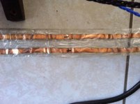
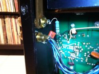
pic of cable ..:
I cant sum two speakers on one channel as you suggested, Z-min would be .5
ohm, the amplifier sonics changes when below 1 ohm, it's why i made the load 1 ohm, 1-1.5 gave me best sonics, 1ohm had best drive, below this the tonal balance on all the amps i have tried changes, kills the sonics. What about playing in mono , i have done this and observed what you have suggested with different wires, but into a stereo L/R mono signal .
IMP is a straight line from 250hz to 22K, except for the slight increase to 1.5 at xover between mid/twt ...
pic of cable ..:
Attachments
Last edited:
JN,
I cant sum two speakers on one channel as you suggested, Z-min would be .5
What about playing in mono , i have done this and observed what you have suggested with different wires, but into a stereo L/R mono signal .
IMP is a straight line from 250hz to 22K, except for the slight increase to 1.5 at xover between mid/twt ...
pic of cable ..:
The reason for using one channel is to make sure that both cable/speakers receives the exact same voltage. Using two channels with mono does not remove that confounder. Two channels in mono is of course a valid test, but it includes what the amplifier does under the load, I want to remove the amp from the equation.
It doesn't matter what the two speaker load does to the sonics, you're not testing that. You are testing to determine if the cable/load characteristics alters the signal sufficiently that you can detect a sideways shift in part of the image spectrum. For example, if one cable causes a sufficient delay that the sibilance of a vocal shifts off center with respect to the rest of the musical content, then the cable made a difference.
I specified using the speakers and sweetspot imaging so that you are using the unshifted image as a physical reference in space, and gauging side shift with respect to the unshifted image.
To try doing this without a central image to reference from means you'd have to control head position with a vice..
edit..BTW, you've ruined the frequency response of your cables. The electrons are going to avoid the plus and minus magic marker symbols , and that's gonna slow the signals down. Maybe you can counter it with red racing stripes on the other side of the cable..😉
jn
ps..I won't tell anybody about that missing pc land if you don't...
Last edited:

..
edit..BTW, you've ruined the frequency response of your cables. The electrons are going to avoid the plus and minus magic marker symbols , and that's gonna slow the signals down. Maybe you can counter it with red racing stripes on the other side of the cable..😉
No. Coulomb's Law. They will be attracted to the + symbol and repelled by the - symbol.
"Ceci n'est pas une pipe."
No. Coulomb's Law. They will be attracted to the + symbol and repelled by the - symbol.
"Ceci n'est pas une pipe."
Ah, but you forgot, my three dimensional friend. They are flatlanders, and cannot discern the symbols as they approach..they only know that such symbols are the work of the demon (Maxwell's demon), so go out of their way to avoid it.. Course, they can't eat either.
Cold enough for ya?
jn
Excellent link Scott. No Bessel maths for me but now I can understand jn’s objection ref your earlier link’s calculations (there are many other jn-mantra in there).
Jn Thanks again for this new battery of posts (all filed)
Dielectric Constants of various materials
Heck! These days I am measuring Rin, Rout at up to 200MHz and I say how sweet it is to work with AF only!
George
Jn Thanks again for this new battery of posts (all filed)
There is a question in my mind for a long time now about the extend of the applicability of the formula L*C=1034*diel. coeff. but I will chew it a bit more.(due to field existing outside the conductor pair).
Dielectric Constants of various materials
The rate of change of the audio voltages is very slow in comparison to the wire lengths we discuss
Heck! These days I am measuring Rin, Rout at up to 200MHz and I say how sweet it is to work with AF only!
George
There is a question in my mind for a long time now about the extend of the applicability of the formula L*C=1034*diel. coeff. but I will chew it a bit more.
George
For constrained cables using a dielectric with free space permeability, the equation holds. This is for coaxial cables, and striplines sufficiently wide with respect to the conductor spacing that most of the field is within the dielectric.
I like it just for the conceptual understanding it gives for the LC relationship, the prop velocity, and when given L and C, easily allows calculation of the DC. you can use the relative permittivity times the relative permeability as well.
For unconstrained cables like zip, I sub EDC, or effective dielectric constant, to reflect the lack of field control.
Also, the prop velocity will be either c/sqr(DC), or c/sqr(EDC) as well. c being lightspeed
Or, 1/sqr(LC) for velocity as well. Just be aware of units..I use 1034 so that the units of L are nH per foot and C is pf per foot. Using 1/sqr(LC) requires attention to that scientific notation stuff..
I'll use DC = LC/1034 to verify somebody's cable measurements as well. If somebody says their cable is 10nH per foot and 50 pf per foot, that gives a DC of about .5. A DC of 1 is lightspeed, so any DC below 1 is superluminal.
jn
Last edited:
Seriously though, this delay stuff has been measured by Cyril Bateman at audio frequencies using a modified RF bridge.
http://techdoc.kvindesland.no/radio/passivecomp/20061223155312558.pdf
George
Attachments

Is this thread still about audio, or is it a kind of strange personal exhibition?
What an interesting question to be asked, especially in this thread..
Are you serious?😕
We are discussing the concepts surrounding the hf impedance of the speaker wire feeding a wildly varying load impedance, and it's impact on soundstage and virtual image integrity.
I thought you were interested in high end audio??
ps. I don't make nasty personal comments when the discussion goes over my head, so I would hope for the same courtesy from you.
jn
Much obliged (again).
you can use the relative permittivity times the relative permeability as well.
Good old Heaviside 🙂
Using 1/sqr(LC) requires attention to that scientific notation stuff..
“Tout comprendre c’est tout pardoner” 😀
I'll use DC = LC/1034 to verify somebody's cable measurements as well. If somebody says their cable is 10nH per foot and 50 pf per foot, that gives a DC of about .5. A DC of 1 is lightspeed, so any DC below 1 is superluminal.
Years ago, I tried the formula to estimate the L of some cables but I failed miserably due to the field spread of these constructions (I didn’t know that then but I suspected it).
http://www.diyaudio.com/forums/multi-way/15600-i-dont-believe-cables-make-difference-any-input-60.html#post209127
There was better control with two ribbons, one (+) on top of the other (-) and even better with a three ribbon sandwich construction (-) ribbon on top, (+) ribbon in the middle, (-) ribbon at the bottom.
Thank you for your insightful input, PMA.
Next time you’ll bring the issue of speaker cables and interconnects, as well as digital interconnects, have a second look on jn posts
George
Personally, I feel that the structure of the cable is too flimsy, considering the currents that are drawn by the speaker. I would mount the foil on a much more rigid substrate, or stabilise what you have there on some form of backing material. What I would look for would be audible variations with peak signals, crescendos and suchlike ...pic of cable ..:
Seriously though, this delay stuff has been measured by Cyril Bateman at audio frequencies using a modified RF bridge.
https://community.klipsch.com/index.php?app=core&module=attach§ion=attach&attach_id=86522
George
- Status
- Not open for further replies.
- Home
- Member Areas
- The Lounge
- John Curl's Blowtorch preamplifier part II