Sergio,
Looks like a discrete version of the MAX6126 circuit mentioned in #44631 ?
Patrick
I don´t think so, in my ccs the noise will be much lower because the use of C1.
MAX6126 uses a shunt ccs , I use a mirror. The output impedance is 100M with the Jfet and 1.5M without them. It is a simple circuit but it gets the job done 😉
I also like the floating bjt ccs . But don´t see any improvment in relation to a simpler jfet floating ccs.
> I also like the floating bjt ccs . But don´t see any improvment in relation to a simpler jfet floating ccs.
That I agree. Still a nice circuit. 🙂
Which voltage reference are you using ?
Patrick
That I agree. Still a nice circuit. 🙂
Which voltage reference are you using ?
Patrick
I've heard this is the best thread here at diyAudio; is that true? 🙂
Recommended safety kit for partaking in the Blowtorch thread.
Attachments


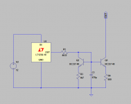
I normally use something like this, use a voltage reference chip of 10v with low Temperature Drift, better to use a dual transistor for Q1, Q2.
C1 will filter the noise from the voltage reference chip and will shunt the base of Q1 to ground, j1 is optional and serves to increase the output impedance (I never use J1).
Even with a tl431 the noise is very low. but of course a low noise chip is prefered.
unless ur Vref is a battery I can't see how the circuit you show will work.
did I miss something ?
> I also like the floating bjt ccs . But don´t see any improvment in relation to a simpler jfet floating ccs.
That I agree. Still a nice circuit. 🙂
Which voltage reference are you using ?
Patrick
to tell you the truth I use tl431, because I got very good result with it. tl431 is a bit noisy, but c1 filter all the noise.
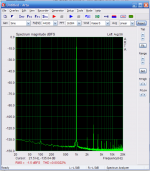
first picture is the measurement of a dac based on pcm1794 where the sink ccs is based on this ccs, output voltage is 2volts rms.
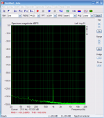
the second picture is the same dac at -110db signal.
As you can see the noise floor is real low.
Attachments
Last edited:
unless ur Vref is a battery I can't see how the circuit you show will work.
did I miss something ?
that circuit represents a structural idea, not a functional circuit.
I assumed that people know how a reference voltage chip works. 🙂
Where is the improved performance come from ?
LT1009 ?
Patrick
The first circuit runs the same transistors at a large current ratio so there is a delta Vbe TC. Roughly 8:1 > ~54mV gives ~ 125uV/C on the voltage across the 600 Ohms. If you go through the analysis after about .25 to .5 Volt degeneration you start losing the noise contribution of the transistors and approach sqrt(4KT/R) for the current noise.
On another point, has anyone ever looked at Vbe variation on parts pulled consecutively off of tape and reel or equivalent. I suspect it is smaller than one might guess.
Last edited:
No. Is the location of the Q2, this transistor compensate the temperature variation in Q1, this circuit assumes a zero tempo for the reference voltage.
the lt1009 can be other reference of 5v. as long it has a decent temperature stability.
the lt1009 can be other reference of 5v. as long it has a decent temperature stability.
That is only true if both legs have the same current.
So for 8mA output, I need to live with a consumption of 16mA.
Right ?
Patrick
So for 8mA output, I need to live with a consumption of 16mA.
Right ?
Patrick
Just don't try to "friend" or tweet me OK. 🙂
No worries...I'm too busy on Nelson's and John's trail of breadcrumbs.
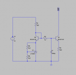
You can have a consumption of 10,7ma with something like this.
Now the temperature stability is even better. And PSRR will be also high.
the ccs ( I1 ) can be a lm134 or similar. In the datasheet of lm134 there is a circuit to compensate the lm134 to zero tempo.
Now the temperature stability is even better. And PSRR will be also high.
the ccs ( I1 ) can be a lm134 or similar. In the datasheet of lm134 there is a circuit to compensate the lm134 to zero tempo.
Attachments

No. Is the location of the Q2, this transistor compensate the temperature variation in Q1, this circuit assumes a zero tempo for the reference voltage.
Not if the current density ratio in the transistors is 8:1, there will be a TC. I see you fixed it.
EDIT - maybe we are experiencing a post shuffling time loop.
Last edited:
On another point, has anyone ever looked at Vbe variation on parts pulled consecutively off of tape and reel or equivalent. I suspect it is smaller than one might guess.
🙂 no, never look, but it makes sense.
Not if the current ratio is 8:1 there will be a TC.
In the second circuit (#44651) the current ratio is 1:1
First circuit was a mistake. 🙂
Last edited:
- Status
- Not open for further replies.
- Home
- Member Areas
- The Lounge
- John Curl's Blowtorch preamplifier part II