PNP transistors are always quieter than NPN transistors.
Only if all else is equal. I doubt if a 2N2907 is quieter that a 2N4401.
Now to talk about optimum topology:
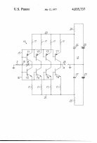
Previously, I put up 4 separate schematic diagrams of different approaches to circuit topology, that were available in 1968, or 45 years ago.
Now I could like to briefly comment on each of them as to their specific characteristics.
The first (A) is just a simple transistor. It could be NPN or PNP, but I drew it with PNP to emphasize that PNP's are quieter for voltage noise, (as shown with the QuanTech) than an NPN. You just have to think 'upside down' and you automatically get a noise improvement. This is the most basic active circuit possible, it can either be common base or common emitter, and it has fairly low noise, IF the device used is the RIGHT ONE. The weaknesses of this topology is high distortion and the need for both emitter and collector cap coupling (at a minimum). Local resistive feedback will increase the input noise significantly, if used. Overall feedback is difficult, because this topology has so little gain in a realistic design.
B is a paralleled combination of input transistors of A. It is 6dB QUIETER, but the base current would be 4 times more, and this could be a problem.
C is a simplified example of what one might do, IF they want to get the lowest noise, yet use an OP AMP to supply more gain, voltage swing, and feedback.
This sort of topology is even used today, perhaps with paralleled N channel jfets, but it could have been implemented 45 years ago, as well.
It is a pretty good approach, if you can get the biasing right, but it is a relatively expensive solution, especially 45 years or so, ago. A number of ultra low noise lab preamps are made with this approach. Generally the input noise is the noise of the input transistor or jfet, and its usually necessary feedback resistor.
Now here is where it gets interesting. How do you get 10 ohm equivalent noise IF you already have a 10 ohm resistor that is in series with the input device(s)? This is a dilemma!
Finally, D shows what most people would opt for, based on what they are used to, a differential pair. It is simple, lower distortion than a single device, easier to bias, BUT it is 3 db NOISIER than a single device.
The fundamental limitation of this input stage, EVEN with virtually perfect devices, makes it 2.5 times or more, noisier than what we could do 45 years ago. And that is why this is a good, but not an optimum approach with MC cartridges.
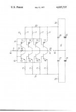
Last edited:
However, you just made the same fundamental mistake that Dick Burwen did at the time. You presumed that all transistors with similar ratings are made essentially the same way. The 2N4403 is the TRUE complement to the 2N4401 and it is quieter than the 2N4401. (At least it used to be)
The 2N2907 has the 2N2222 as a complement. The Rbb' of these devices is greater than the 2N4401-2N4403 devices. The QuanTech sorted this out for me in 1968.
The 2N2907 has the 2N2222 as a complement. The Rbb' of these devices is greater than the 2N4401-2N4403 devices. The QuanTech sorted this out for me in 1968.
so what "isn't equal" in op amps? - the low noise bjt inputs I see in simplified schematics are NPN
In discrete bipolar transistors, the PNP complement usually has about 1/2 the Rbb' or intrinsic base resistivity. IC's have had problems with making PNP transistors.
However, you just made the same fundamental mistake that Dick Burwen did at the time. .
Sorry John I knew exactly what I was saying you made a blanket statement that could mislead someone with less knowledge. This stuff is basics, ALL pnp's are not quieter than ALL npns. Complimentarity in bi-polars is fairly loose they all have the same gm vs current we usually differentiate on ft and beta/VA product.
I don't make fundamental mistakes (except that I forgot copper is never superconducting).
I don't make fundamental mistakes (except that I forgot copper is never superconducting).
And I'll never allow you to live that one down...😀
jn
You did not read my statement to Demian very carefully, Scott. In the next sentence, I stated: "The Rbb' of the PNP is usually about 1/2 the value of the NPN transistors, WITH SIMILAR CONSTRUCTION."
The 2N4401-2N4403 are the complements that really work better than almost all preceding part pairs for low voltage noise, AND they were NOT represented as low noise devices at the time.
The 2N4401-2N4403 are the complements that really work better than almost all preceding part pairs for low voltage noise, AND they were NOT represented as low noise devices at the time.
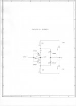
Now, if I can, I would like to give an alternative approach to the low noise problem.
This is not necessarily a universal solution, and I personally haven't used it for the last 30 years, BUT this does give low noise without an input transformer.
The advantages of this design is that it can run on a couple of D cells, and this lowers the price and gives a relatively quiet power supply. It is direct coupled both input and output, BUT it does not amplify DC. Even 45 years ago, (if I had thought it up at the time) it could achieve the equivalent noise of a 10 ohm resistor, and this became the Levinson JC-1, in 1973. (schematic as soon as I find it)
schematic
John, any chance of making the jpg a bit larger? The image is almost the same size as the thumbnail on my computer.
jn
It will amuse you to know that when it came out, ESS we were using dental
tools to open the encapsulated circuits.
😎
tools to open the encapsulated circuits.
😎
Here is a simplified schematic of the same topology. With IMPROVED transistors,(different part numbers), this was all that was necessary, 33 years ago. However, for the 2N4401-3 combination, multiple pairs were necessary.
I don't see different part numbers, do you mean the Rhom complimentary pair?
BTW, someone showed me a fully complimentary npn/pnp amp from 1967 (high speed not audio).
so what "isn't equal" in op amps? - the low noise bjt inputs I see in simplified schematics are NPN
This is a really funny issue sort of like righty/lefty. Single supply op-amps frequently are pnp input so they go to ground, but without this constraint folks go right to npn's and you know I never did an rbb study for the 797. The beta/VA is inferior on the pnp's and that also goes with the dopants, this is true until you get to some of the exotic processes they have now. This might be the real issue.
Of course I have ...Ok , so you have never personally heard any of them , nor have you ever heard the sound you speak off ..
I'll use an analogy. People make movies, and the best way to make a realistic movie, in the visual sense, is to go on location, and have all the props being items that are part of the 'real' world. Then, every tiny aspect of the appearance of the surroundings in the movie always works, there is never a single artifact that gives the "game away".
Now, to save money and because of safety, logistics, the sheer impossibilities, move makers fake it. A noble art has evolved over the years, and it has evolved - look at the old movies now and you inwardly laugh, or wince, at times, the clumsiness of the fakery turns the scene into high camp - to our more sophisticated eyes. Yet, mature adults back then took it all in - they were terribly impressed by what appeared on the screen.
So it is in audio. Most clips of sound reproduction stink of fakery, the sound you hear is obviously a hifi system pretending to mimic real sounds, as compared to the accompanying 'real' sounds in the video - it's usually chalk and cheese. Especially very expensive systems at hifi shows - quite often sound absolutely ridiculous in the video.
A sound system that reproduces convincing, big sound in the flesh will also record well, the sound of it won't give the game away, you have to look at the visuals to realise that that the audio is a reproduction, not the real thng ...
In movies, they deliberately 'camp up' the sound to make sure you know that a sound in the scene is supposed to be coming from, say, a radio - make it sound really fake ... working in reverse, this time ... 🙂
- Status
- Not open for further replies.
- Home
- Member Areas
- The Lounge
- John Curl's Blowtorch preamplifier part II