
I turned on this amp tonight. Blew up a few parts. I will have to rebuild it next week and get some more fuses.
Try the initial start-up with reduced primary (or sec) voltage to help avoid creating that dreaded genie smoke (variac, etc) - can often measure errors before "killing silicon" - be interesting to compare this amp to maybe a KSA100.
wow, too bad.
hope you didn't loose the jfets!
🙁
do you know what went wrong? maybe starting up with the bias pot fully opened?
btw, by tying the 80k feedback resistor to one side of the bias generator, and leaving the output devices out, you could check the general functionality of the input and VAS stages.
mlloyd1
MikeW said:I turned on this amp tonight. Blew up a few parts. I will have to rebuild it next week and get some more fuses.
Thanks for the support. I took the outputs out of the circuit. I must have blown up one of the BD 139"s or 140"s. I was trying to trouble shoot and Q1 melted it's solder. At least I know thw power supply will put out plenty of current. I am sure it will work sooner or later. I have more parts. This is the fun part.

One of the reasons I've been holding back with my amp is to give you a chance to get yours established. Good luck with your trouble shooting.
Grey
Grey
Mike,
if you like it hot you should take your Donzi way down south and become a coke runner, i've got a USCG friend who'd be more than happy to point a bigger soldering gun at ya.
if you like it hot you should take your Donzi way down south and become a coke runner, i've got a USCG friend who'd be more than happy to point a bigger soldering gun at ya.
I sold the little Donzi. All that if left is a 27 ft. Fountain.
Do any of you guys need any resisters? I have a couple of reels that I will never use.
Do any of you guys need any resisters? I have a couple of reels that I will never use.
About 15 1% and 15 5%. Mostly 1/4 watt but some 1/8 watt. All different types. Anything specific that you need?
MikeW said:All that left
I wouldn't say no to a 47ft Javelin with triple 502EFI's either, but overhere a Reggie Fountain is considered pretty big for a powerboat.
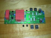
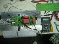
Some note from test 2.
The power supply is +/- 26
R 25 should be 50 ohms or higher or heatsinks will be needed for Q1 and Q10.
The emitter output resisters are .51 ohms. Bias is set to 1 amp.
Values wrong on the schematic. (R5,R17 are 10 K and R14 is 1 ohm)
I added C10 and C11 (130 pf.) because of an high frequency oscillation.
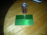
I need to clean this up and build the other channel.
dimitri, did your get your parts?
The power supply is +/- 26
R 25 should be 50 ohms or higher or heatsinks will be needed for Q1 and Q10.
The emitter output resisters are .51 ohms. Bias is set to 1 amp.
Values wrong on the schematic. (R5,R17 are 10 K and R14 is 1 ohm)
I added C10 and C11 (130 pf.) because of an high frequency oscillation.
I need to clean this up and build the other channel.
dimitri, did your get your parts?
Attachments
yes, thanksdimitri, did your get your parts?
do you have C8, C9? try to remove C9
- Home
- Amplifiers
- Solid State
- John Curl amp