Huh?
I can only assume you didn't read my post correctly, may I please ask that you do.
I didn't rule the amp out in toto - I simply responded to comments that said that frequency response changes was the reason for the sound changes. They are NOT. You have just confirmed that, so you confirmed that I have proved that is not the case. So please, maybe reconsider your comments. Mine are are about as clear as can be made.
I never rule out the amplifier - most aren't that good.
Again, this 'social media' stuff is seriously flawed when you can say one thing and be accused of saying the opposite. I don't think I will ever get used to that.
OK then. I have no problem with it and I can believe that the difference it's not just down to a small difference in a narrow portion of the frequency range.
Oh, wow. Now we have Lynn brought into the argument. I will not denigrate Lynn but I will say emphatically that you can not have it both ways. This is 60's audio spin vrs the real world of the 2010s. You can not go around claiming you can hear things that can not be measured or explained on the on hand and then deny the audibility of things that are clearly measurable and of a magnitude that is widely accepted as audible on the other. It's just smacks of a lack of credibility.
As Mark said, the only thing that is proven from any of you plots is that your comp network does not render the impedance flat and resistive, which was apparent on page 1.
To be honest I don't understand the need to make all these unsubstantiated claims. It's it enough to say that your crossover has smoother response than the original Usher and that the addition of the comp network allows the speaker to be relatively insensitive to amplifier output Z?
It's it enough to say that your crossover has smoother response than the original Usher and that the addition of the comp network allows the speaker to be relatively insensitive to amplifier output Z?
That appears a conclusion that is totally supported by all we have seen here. As well as by common sense.
Jan
Of course it's not totally flat. How can you equalise a double-peak reflex with a single LCR?
But I think we have had plenty of explanation of why it works better. Admittedly drowned out by all the carping.
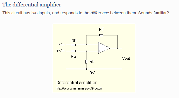
Ask yourself what happens to common-mode when one of the inputs (V+ or V-) is actually grounded rather than in balanced mode. Now it looks like noise from the Earth rail in an unbalanced system. Now do you get it? I couldn't have explained it more simply. 😎
Now we COULD actually be extending Joe's impedance ideas, but if you want to go nowhere for another 100 pages, I can't stop you. TBH, I'm having a much more interesting discussion with Joe via PM. 😀
But I think we have had plenty of explanation of why it works better. Admittedly drowned out by all the carping.
You, like a lot of people in this thread aren't listening or learning, are you? You are just trying to score points. 🙄No. Common mode is just what it says: it is a signal that is the same on both inputs (the signal input as well as the feedback input).Originally Posted by system7
Joe you were asking how common-mode distortion works in amplifiers, having dealt with transistor Class AB crossover distortion. It's noise from the Earth Rail that finds its way into the signal input.
As such a signal goes up and down, both inputs go up and down identically and in an ideal setting, there would be no output signal from the amp.
Of course things are not ideal and there WILL be an output signal. How much, depends on the common mode suppression capabilities of the amp.
Common mode distortion is when the presence of that 'both-sides-equal' signal causes distortion of the wanted signal (logically called differential signal). In transistor input stages for instance this is caused by the fact that the input impedance changes with input level. But that's for next time 😉
Jan
Ask yourself what happens to common-mode when one of the inputs (V+ or V-) is actually grounded rather than in balanced mode. Now it looks like noise from the Earth rail in an unbalanced system. Now do you get it? I couldn't have explained it more simply. 😎
Now we COULD actually be extending Joe's impedance ideas, but if you want to go nowhere for another 100 pages, I can't stop you. TBH, I'm having a much more interesting discussion with Joe via PM. 😀
Steve, there have been no coherent explanations from Joe as to why it should sound better or why this is a low noise design. Sy did ask back in post#3.
I am not sure about others, but I don't understand what you are trying to demonstrate with your last post.
I am not sure about others, but I don't understand what you are trying to demonstrate with your last post.
Ask yourself what happens to common-mode when one of the inputs (V+ or V-) is actually grounded rather than in balanced mode. Now it looks like noise from the Earth rail in an unbalanced system. Now do you get it? I couldn't have explained it more simply. 😎
Unfortunately your explanation is still completely wrong. When one input gets ground noise as you say, it is differential mode (noise on one input and not on the other). I can't fathom why you would call that common mode. The name says it: 'common'.
Now, in your example, if somehow BOTH inputs would be soiled with the same ground noise, THAT would be common mode and would be cancelled, to some extend, by the differential amplification.
That's alright - I like to set things right.
Jan
Steve, there have been no coherent explanations from Joe as to why it should sound better or why this is a low noise design. Sy did ask back in post#3.
I am not sure about others, but I don't understand what you are trying to demonstrate with your last post.
I haven't done calculations but can imagine that also a low Zout amp is "transformed" into a "high" Zout amp through his x-over. "high" because the one presented here is not really high in my book but ok to get close.
The current drive removes (reduces) compression which happens with low Zout amps working as they should. The compression is due to the fact that the force one wants to use to control the driver is not acting on the same basis as the driving force. With current drive damping (stopping) of its motion is left to the driver only in theory and almost entirely in practice. So the driver has to be a good one and design of the speaker too. So the noise Joe was talking about is the compression that has been removed with current drive. He calls it better clarity.
I am very confident about this because I have got some experience with current driven loudspeakers. The only differences with the one presented here are: the cost (expensive stuff but still cheaper than typical hi-end rubbish), the absence of crossover and flat FR achieved with dedicated drivers thought and engineered to be driven this way. In this case the impedance is not even as flat as the one presented here.
Last edited:
Except that it isn't noise by any stretch of the imagination. Compression is the exaggerated rounding or flattening of the wave tops and bottom. Plain vanilla odd harmonic distortion.
Anyway, I still have no idea of the configuration that those screen shots are about. I asked the question a few posts back but true to form no answer is forthcoming, except some veiled wording hinting that my agenda would be dishonest. Ohh well.
Jan
Anyway, I still have no idea of the configuration that those screen shots are about. I asked the question a few posts back but true to form no answer is forthcoming, except some veiled wording hinting that my agenda would be dishonest. Ohh well.
Jan
Except that it isn't noise by any stretch of the imagination. Compression is the exaggerated rounding or flattening of the wave tops and bottom. Plain vanilla odd harmonic distortion.
Anyway, I still have no idea of the configuration that those screen shots are about. I asked the question a few posts back but true to form no answer is forthcoming, except some veiled wording hinting that my agenda would be dishonest. Ohh well.
Jan
Well I don't want to get into wording game but it sounds like that to me and surely is distortion but not harmonic distortion.
I haven't done calculations but can imagine that also a low Zout amp is "transformed" into a "high" Zout amp through his x-over. "high" because the one presented here is not really high in my book but ok to get close.
The current drive removes (reduces) compression which happens with low Zout amps working as they should. The compression is due to the fact that the force one wants to use to control the driver is not acting on the same basis as the driving force. With current drive damping (stopping) of its motion is left to the driver only in theory and almost entirely in practice. So the driver has to be a good one and design of the speaker too. So the noise Joe was talking about is the compression that has been removed with current drive. He calls it better clarity.
I am very confident about this because I have got some experience with current driven loudspeakers. The only differences with the one presented here are: the cost (expensive stuff but still cheaper than typical hi-end rubbish), the absence of crossover and flat FR achieved with dedicated drivers thought and engineered to be driven this way. In this case the impedance is not even as flat as the one presented here.
The thing is that you don't need any compensation networks for a current driven speaker if it is of active design. On the other hand, if it's passive then here is the thing. Consider a single driver in in a box driven by a voltage source. You measure it and it has a high pass response with a certain Q. Now you driver that same box with a current source. It will have a much higher Q. So, if you want to same Q you add an appropriate shunt network. This is nothing but passive equalization so that th4e current through the VC is the same as the voltage drive case, and it will restore all the electrical damping that was present with the voltage source because the eq network will provide the low impedance path for current associated with the back EMF generated in the motor structure and/or release of stored energy to stop the driver motion. That is, the system amp, network and driver/box to have the same response it must have the same damping.
EDIT:
As for asking if placing a large series resistance in series with a speaker makes the speaker behave as if it's connected to a current source, the answer is yes. I've done the math. Distortion components in the back EMF, which generate distortion in the drive current, diminish in magnitude as the series resistance increases. Thus the distortion in the drive current becomes the same as that associated with the distortion in the ampere's output voltage as the series resistance goes to infinity. But we must realize that the back EMF peaks around resonance and decays at 6dB/octave to either side.
Last edited:
Well I don't want to get into wording game but it sounds like that to me and surely is distortion but not harmonic distortion.
It is harmonic distortion because it is related to the signal. Draw it or sim it.
Compression generates spectral lines that are harmonics of the signal.
BTW You know, I like mirror images. In this case, the mirror image of compression is expansion. Same difference, same harmonic components, different phase.
Electric guitar players LOVE compression and expansion ;-)
Jan
Last edited:
The thing is that you don't need any compensation networks for a current driven speaker if it is of active design. On the other hand, if it's passive then here is the thing. Consider a single driver in in a box driven by a voltage source. You measure it and it has a high pass response with a certain Q. Now you driver that same box with a current source. It will have a much higher Q. So, if you want to same Q you add an appropriate shunt network. This is nothing but passive equalization so that th4e current through the VC is the same as the voltage drive case, and it will restore all the electrical damping that was present with the voltage source because the eq network will provide the low impedance path for current associated with the back EMF generated in the motor structure and/or release of stored energy to stop the driver motion. That is, the system amp, network and driver/box to have the same response it must have the same damping.
EDIT:
As for asking if placing a large series resistance in series with a speaker makes the speaker behave as if it's connected to a current source, the answer is yes. I've done the math. Distortion components in the back EMF, which generate distortion in the drive current, diminish in magnitude as the series resistance increases. Thus the distortion in the drive current becomes the same as that associated with the distortion in the ampere's output voltage as the series resistance goes to infinity. But we must realize that the back EMF peaks around resonance and decays at 6dB/octave to either side.
The loudspeakers and the current amp I have experience with have no compensation network, large resistors and crossover. There is only one capacitor in series with the tweeter. The amplifier has 1 Mohm output impedance and only three (3) components in the direct path of the signal. I know them very well because a dear friend of mine has the full system. And yes it is a commercial product.
It is harmonic distortion because it is related to the signal. Draw it or sim it.
Compression generates spectral lines that are harmonics of the signal.
BTW You know, I like mirror images. In this case, the mirror image of compression is expansion. Same difference, same harmonic components, different phase.
Electric guitar players LOVE compression and expansion ;-)
Jan
I though he was referring to thermal compression. Seems that what your are referring to is what might also be called soft limiting where peaks are compressed as oppose to a linear reduction of amplitude due to an increase in VC resistance.
Isn't the VC temperature modulated by the signal? Are you saying that the thermal modulation at low frequencies follows the signal wave form, while at higher frequencies it follows the signal envelope? Similar to thermal value modulation of resistors?
If that is the discussion I would say that at lower frequencies harmonics are generated (non-linear distortion) but at at higher frequencies you get what is sometimes called linear distortion.
Jan
If that is the discussion I would say that at lower frequencies harmonics are generated (non-linear distortion) but at at higher frequencies you get what is sometimes called linear distortion.
Jan
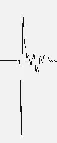
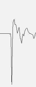
To see what current drive does just measure the impulse response of a woofer in air, do the same with a voltage drive and compare them. This just to rule out other "components". It will be self-evident that the former is far better. Also the decay is shorter and cleaner.
Last edited:
Isn't the VC temperature modulated by the signal? Are you saying that the thermal modulation at low frequencies follows the signal wave form, while at higher frequencies it follows the signal envelope? Similar to thermal value modulation of resistors?
If that is the discussion I would say that at lower frequencies harmonics are generated (non-linear distortion) but at at higher frequencies you get what is sometimes called linear distortion.
Jan
Well, now I'm embarrassed. I should pay more attention to work I have done in the past. 🙂
VC Heating
To see what current drive does just measure the impulse response of a woofer in air, do the same with a voltage drive and compare them. This just to rule out other "components". It will be self-evident that the former is far better. Also the decay is shorter and cleaner.
If you accept that a voltage source with high output Z mimics a current source (which my analysis shows is true), I'll post some data tomorrow.
If you accept that with a current source only mechanical damping is present, then
An externally hosted image should be here but it was not working when we last tested it.
So the current source is supposed to have a shorter decay?
This is a real measurement. I know it's counter-intuitive but that is.
I do run simulations for work but I know they work.
I don't do it for audio because it's just a hobby for me. Only run some measurements sometimes to verify I am really getting what I think.
Attachments
Last edited:
So the current source is supposed to have a shorter decay?
Loaded example… the target for a woofer used with a current source amp is that Qms <1
dave
- Status
- Not open for further replies.
- Home
- Loudspeakers
- Multi-Way
- Joe Rasmussen Usher S520 "Current Compatible" Crossover