Joe,
I found an mention of silver and carbon being utilized in an multi-gang 9mm Alps/Alpine potentiometer, series RK097. The description is intriguingly similar to that Alpha pot. from Jaycar.
The mention is in the below linked page, about the fifth paragraph down.
I found an mention of silver and carbon being utilized in an multi-gang 9mm Alps/Alpine potentiometer, series RK097. The description is intriguingly similar to that Alpha pot. from Jaycar.
The mention is in the below linked page, about the fifth paragraph down.
Anyone compared this amp to FirstWatt F5 or J2 on a pair of Elsinores?
The transamp is a current amplifier and should be compared to
First Watt F1 or F2, the only First Watt current amps.
The transamp is a current amplifier and should be compared to
First Watt F1 or F2, the only First Watt current amps.
Ok, thanks for the clarification, but I have parts for the F5 and J2. Just want to know wich one to build from a subjective standpoint. Wich one sounds best driving a pair of Elsinores?
The transamp is a current amplifier and should be compared to
First Watt F1 or F2, the only First Watt current amps.
But the flat impedance of the Elsinore Mk6 means that it cares not what the amlifiers Zout is so the comparison becomes meaningful
If the loudspeaker had an impedance more like typical speakers with XOs (ie all over the map) then your statement is valid.
That said, Joe’s amp is an inexpensive chip amp, i have heard its pre-cursor (designed an dbuilt by a buddy) and it is really quite excellent,
The F5 & J2 are discrete amps from the genuis of Mr Pass, neithe rof which i have heard, but i expect they would have an edge, albeit at a much greater entry price.
It is worth noting that the 4Ω output impedance of the F2 puts it on the voltage amp side of the cross-over point with a Zout closer to many SETs.
dave
Joe, I know this is an old thread, but I hope you do not mind few questions before I burn few chips. I was recently experimenting with transconductance lm1875 amps, and they are all working fine and singing beautifully, so I feel the need to work with lm3886 next (because I have plenty).
Can one substitute lm3875 with lm3886, assuming correct pins are used, without any changes to the schematics in first post?
Can one put trim pot on the positive rail side if needed? Could one do trim pot between the rails, to make it universal?
Thanks!
Can one substitute lm3875 with lm3886, assuming correct pins are used, without any changes to the schematics in first post?
Can one put trim pot on the positive rail side if needed? Could one do trim pot between the rails, to make it universal?
Thanks!
Hi all and adason,
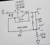
If you connect an electrolytic capacitor from 100 to 220 uF (best bipolar) between pins 8 and speaker ground, it does not generate an off-set imbalance and does not need to do a "DC trim". You must also use a 22k resistor between pins 8 and 3, at the output. It was JMFahey-Argentina's orientation for an LM1875 chip.
If you connect an electrolytic capacitor from 100 to 220 uF (best bipolar) between pins 8 and speaker ground, it does not generate an off-set imbalance and does not need to do a "DC trim". You must also use a 22k resistor between pins 8 and 3, at the output. It was JMFahey-Argentina's orientation for an LM1875 chip.
great, but can you be more specific which chip and which pin number are you talking about?
ideally, post schematics or a link
3875 and 3886 only share first few pins, but second half is different
1875 does not share any pins
ideally, post schematics or a link
3875 and 3886 only share first few pins, but second half is different
1875 does not share any pins
I added an OP amp with a LP filter 0.01Hz from output to signal input and added a series resistor of 47kohms from output of the OP amp to the input of x amplifier...
Thanks, i got that one up and running. Sounds sweet and musical. Now i am working on lm3886 and have some dc on the output, in some cases positive, in some negative, hence i was asking about universat trim.
Any specific info about that cap mentioned few posts back would be nice, but schematics would be ideal.
Any specific info about that cap mentioned few posts back would be nice, but schematics would be ideal.
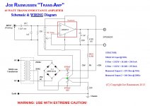
Current amp
Dear adason and all,
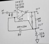
Sorry for the delay, I need to use google translator. This scheme works for the three LM chips. Two I tested, 1875 and 3875. Other components like the schematic Mr. Rasmussen. I already asked for your guidance for these current amplifiers: they sound great.
Dear adason and all,
Sorry for the delay, I need to use google translator. This scheme works for the three LM chips. Two I tested, 1875 and 3875. Other components like the schematic Mr. Rasmussen. I already asked for your guidance for these current amplifiers: they sound great.
Attachments
Thanks! Now the cap placement is clean as a whistle.
Your schematics is different than from Joe in the first post. Yours is using 22k feedback resistor from output to noninverting input. His feedback is not from the output, but after 470 shunt resistor from the output.
Lots to test!
Your schematics is different than from Joe in the first post. Yours is using 22k feedback resistor from output to noninverting input. His feedback is not from the output, but after 470 shunt resistor from the output.
Lots to test!
Hi adason,
It can be just like you drew. But look at the link at Loudthud @ 06: 30h, when JMFahey teaches how to make a current amplifier for guitars: Transconductance LM1875. You can also see a good article by Mr. John Lenard Burnett at the link Amplifiers: Solid State amps verses Valve amps. Forgive my bad English again.
It can be just like you drew. But look at the link at Loudthud @ 06: 30h, when JMFahey teaches how to make a current amplifier for guitars: Transconductance LM1875. You can also see a good article by Mr. John Lenard Burnett at the link Amplifiers: Solid State amps verses Valve amps. Forgive my bad English again.
Last edited:
No. The DC feedback shall come from the output to have unity gain there (and then no need for a DC adjust). Your schematic is fully DC-coupled with the 22k which is simply shorted out by the cap at higher frequencies.augustoriodosul, would this make more sense to be true transconductance amp?
feedback needs to read after the speakers
The "true-ness" of the amp is governed by the 470R parallel resistor and the parallel "snubber" R+C but it is way good enough the way it is for speaker driving. True current drive from DC to 20kHz (Z_out >> 1kOhm) is neither actually required nor a good design requirement to start with, and would be very hard to obtain anyway.
No. 470R resistor does no create 'true-ness' of any kind. Its just there to protect wild voltage swings when speaker is unplugged while running.
When one is careful, it can be omitted, its shunt by speakers impedance anyway.
No. R+C 'snubber', otherwise known as zobel has nothing to do with current drive, its used to shunt high frequencies in any amp.
True key to current drive is 0.33R resistor.
When one is careful, it can be omitted, its shunt by speakers impedance anyway.
No. R+C 'snubber', otherwise known as zobel has nothing to do with current drive, its used to shunt high frequencies in any amp.
True key to current drive is 0.33R resistor.
Attachments

- Home
- Amplifiers
- Chip Amps
- Joe Rasmussen "Trans-Amp" - 40 Watt Transconductance "Current Amplifier"