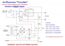
470 ohm resistor: current amplifiers, the higher the impedance of the speaker, the greater the power. The equation is 8 ohm / .33 + 1 = a gain of approximately 25. BUT if you turn off the speaker, the impedance is infinite, burning the amplifier's output. This is the role of the 470ohm resistor: ballast, in case the speaker is turned off. Interestingly Mr. Esa Meriläinen does not mention this device in the book.
that's exactly what I said 🙂
btw, i finished tweaking all four channels (two stereo amps) based on lm3886
i removed zobel and all behaved much better, and no, there are no oscillations, I have oscilloscope
now finishing it in the box, it will be part of biamp system
no need to run classA in summer!
stay safe
btw, i finished tweaking all four channels (two stereo amps) based on lm3886
i removed zobel and all behaved much better, and no, there are no oscillations, I have oscilloscope
now finishing it in the box, it will be part of biamp system
no need to run classA in summer!
stay safe
Thank you adason, keep us informed of progress. Current amplifiers are strikingly easier to perceive for good bass and treble reproduction. Just remember: be careful, they do not behave well in systems with passive network inside the speakers. I used an LM3875 straight on a ribbon tweeter, just put a 6 ohm ceramic resistor in series and it was very good.
@Adason,
Could you show some measurements with the transamp loaded by a woofer, preferably both a nearfield measurement of the woofer plus a measurement of the electric output of the transamp? What PCB have you used?
Could you show some measurements with the transamp loaded by a woofer, preferably both a nearfield measurement of the woofer plus a measurement of the electric output of the transamp? What PCB have you used?
There was a guy called "skylab" of the HK Audio Club who developed some pcbs for this amp - perhaps you could write to him to see if he'd send you the design/layout/tracking - this was back in 2016 - there's a photo of the bottom traces in post #323 to give you some idea - this was their second version, I think
I got the last board they had spare and it was definitely better than any other layout I tried.
I got the last board they had spare and it was definitely better than any other layout I tried.
For our 3875 TransAmp (preDates & helped informed it) used an early modified standard ChipAmp/AudioSector PC board
dave
dave
Esa Meriläinen shows you how to turn any voltage amplifier into a current amplifier. There may be an exception that doesn't work.
this is what works for me right now
i wonder if others can build and compare
most of the time people like the sound of current amp and attribute it to more power in lower frequencies or highs due to increasing resistance getting more power
but i have few systems where I use 31 band digital eq to equalize flat fr response in my listening position
I do this for every change in the system, so comparing apples to apples, I replace application note amp with this transconductance amp, and the result is day and night
application note sounds flat, clean, yet boring
current amp sound musical, juicy, engaging
just like life music
so its not fr response
something else is in the play... phase, timing
what do you think?
Attachments

Hi
If you equalize for flat response both amplifiers you still are not comparing apples to apples. Yes current drive sounds like you described. But with current drive you get less high order harmonics and little more first even order harmonics. Than can be the main reason for better sound. Another reason is that with current drive you have very low damped oscilator.. and expecialy near Fs it changes waveform a lot! Make some sine burst and you will see. This can be fixed with full mathematical inverse for perfect impulse response. But after that current drive still sounds better, so the reason is different HD distribution. I work only with current drive amps. But i use only open baffle type loudspeakers. And only active systems. For box speakers there are less advantages for current drive. Then you can use voltage near Fs and current for higher frequencies. There are other posibilities as well,but they are case dependand. Benefits in one place are drowbacks in another.
If you equalize for flat response both amplifiers you still are not comparing apples to apples. Yes current drive sounds like you described. But with current drive you get less high order harmonics and little more first even order harmonics. Than can be the main reason for better sound. Another reason is that with current drive you have very low damped oscilator.. and expecialy near Fs it changes waveform a lot! Make some sine burst and you will see. This can be fixed with full mathematical inverse for perfect impulse response. But after that current drive still sounds better, so the reason is different HD distribution. I work only with current drive amps. But i use only open baffle type loudspeakers. And only active systems. For box speakers there are less advantages for current drive. Then you can use voltage near Fs and current for higher frequencies. There are other posibilities as well,but they are case dependand. Benefits in one place are drowbacks in another.
wow
so i am using the same cd player, the same signal selector, the same volume buffer, the same equalizer, the same speakers, the same wires, even the same power supply for the amps, just one chip amp based on application note, and the same chip amp in transconductance circuit...
yet its not comparing apples to apples
i wonder what is
my logic just seized
i am outa here
bye
Maybe this is a miscommunication? You say there is still a difference, ok. Apples to apples means the test is fair, but there can also be a difference. The harmonic distortion you mention is an example.you still are not comparing apples to apples.
wow
... the same … same… same… same… same…same.. same...one chip amp based on application note, and the same chip amp in transconductance circuit...
yet its not comparing apples to apples
With one the speakers impedance imposes itself on the sound. What does your speaker impedance look like?
dave
Yes kind of miscommunication. I mean that you are comparing diferent signals. Maybe you think they should be the same.Even if you equalized with parametric equalizer, the signals coming out are not the same for voltage and current drive. So for sure they sound diferent. Linear part of the transfer function is changed. Main reason little damping for current drive.signal change can sound pleasant or unpleasant. And there is unlimited ways to change the signal.So for me from engineering standpoint makes more sense to make linear part of transfer function the same and that means that only nonlinear part differs. Linear part is fully described by single impulse response. Frequency response not enought.
There's another error in that schematic in #489 - the speaker current is supposed to be sensed through the 0.33R resistor, but as drawn the speaker current is not going through it. As drawn it is a voltage drive/voltage feedback amplifier.
Jan
Jan
Actually I think it is correct. Feedback is taken from the top of the resistor and input ground is on the other side of the resistor so the input voltage is imposed on the resistor which determines the current through the speaker.
When you use a current drive amp it is like using your speaker impedance as an EQ curve. The frequency response will be a big confounder if you are trying to listen for differences in distortion, which is the reason for using a current drive amp.
One way to get around this is to use zobels to flatten the impedance curve of the speaker, but then you lose the advantage of current drive.
That would mean that using a current drive amp using Elsinore loudspeakers (flat impedance curve apart from sub 20 Hz resonance) would not make much sense.
That makes ittle sense. Joe flattened the impedance of Elsinore so that it mattered not what the output impedance of the amplifier is. Am ideal opportunity to try out a current amp.
dave
dave
- Home
- Amplifiers
- Chip Amps
- Joe Rasmussen "Trans-Amp" - 40 Watt Transconductance "Current Amplifier"