Hi Joe,
there is max 60DC of the power supply in 1875's datasheet,
you are using +- 35=70V
did the chip survived?
was the radiator very hot?
Maybe it did not heat up because Joe actually uses the 3875 and not the 1875 😉
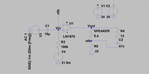
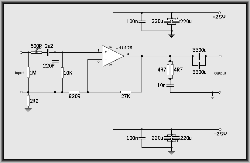
Hi Joe, any opinion about this circuit of current amp? I got plenty of LM1875, if it looks promissing, I may go ahead an built it, just for fun.
Hi
I built similar amp but with shorted R4 and R7 0.33 Ohm,
the resistance of my speeakers is 5.4 Ohm.
The sound quality is extraordinary, indeed like good tube amp, detailed and velvetlike trebles, etc.
The speakers are a little boomy but this not annoys me, it is acceptable.
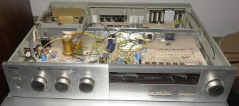
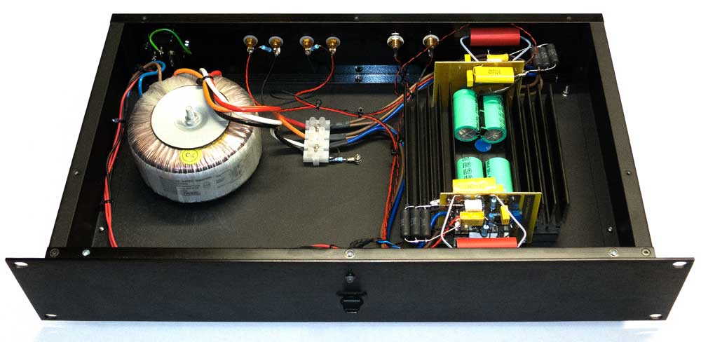
The amp is mounted inside dead Philips F4220 from which I used power supply and input path.
I have large offset at the output (+350mV) and I am going to use 10k pot from negative rail to inverting input to cancel the offset.
I use 7824/7924 regulators decoupled with 470uF/63V Panasonic FC.
Probably soon I will post the pictures.
I tried to listen to the music very loud but the meters of power indicators in the front of the amp were far away bellow 1W!!!
clipping
😕
after mounting inside the enclosure
I can listen only left channel.
When I turn the balance pot max on the left the music is clear and beauty only in left channel.
When I try to put balance pot in the middle both channels are overdriven and clip😱
oscillations???
😕
after mounting inside the enclosure
I can listen only left channel.
When I turn the balance pot max on the left the music is clear and beauty only in left channel.
When I try to put balance pot in the middle both channels are overdriven and clip😱
oscillations???
Attachments
fixed!
the issue solved!
now every amp chip has independent supply (what took only 2XL7824 and 2XL7924C stabilisers for 2XTDA2050) terminated with 470u/100V Muse KZ caps and within burning in process the sound is better and better in every minute.
There is not aggresive sign even with louder levels!
I recommend transconductance amps for good sound lovers!


😎
the issue solved!
now every amp chip has independent supply (what took only 2XL7824 and 2XL7924C stabilisers for 2XTDA2050) terminated with 470u/100V Muse KZ caps and within burning in process the sound is better and better in every minute.
There is not aggresive sign even with louder levels!
I recommend transconductance amps for good sound lovers!
😎
offset...
During the work I burned one TDA2050
and now left channel works with 2050
and the right with LM1875.
For TDA2050 I have the offset 146mV, for LM1875 47mV.
Attached is the schematic with V4 voltage source which is injecting DC voltage to null the offset.
Please propose a precision circuit which could help eliminating the offset in practice, the trick with connecting inverting input to negative rail via 10k potentiometer does not work with those chips...
if the inputs to a tda2050 is a pair of BJT transistors, then the usual rules apply.
The inputs should be sufficiently well matched such that arranging the same resistance for each to the reference voltage SHOULD get a lowish output offset.
Then trimming of one or other resistance can adjust the offset to zero.
The inputs should be sufficiently well matched such that arranging the same resistance for each to the reference voltage SHOULD get a lowish output offset.
Then trimming of one or other resistance can adjust the offset to zero.
Hi
thank you for the respone.
I changed 2050 into 1875 into left channel and the offset was +40mV in both of the channels.
Then I loaded the input resistance R2 of the nonirventing input from 100k to 13k and the offset is now -8mV for the left and -5mV for the right channel.
I guess that ~20k is the value for 1875's to keep the offset closest to zero.
But for me the offset like now is acceptable.
Maybe I will experiment with the input loading in the future?...
Now I have great sounding amp in nice enclosure with power level indicators!!!
After cranking up the volume it not screams, there is only "more of the the music"!
In this post you have information about the use of output capacitor:
http://www.diyaudio.com/forums/chip...-hifi-lm1875-amplifier-board.html#post1513044
http://www.diyaudio.com/forums/atta...i-lm1875-amplifier-board-lm1875-gainclone.gif
http://www.diyaudio.com/forums/atta...clone-hifi-lm1875-amplifier-board-bipolar.gif
Regards
http://www.diyaudio.com/forums/chip...-hifi-lm1875-amplifier-board.html#post1513044
http://www.diyaudio.com/forums/atta...i-lm1875-amplifier-board-lm1875-gainclone.gif
http://www.diyaudio.com/forums/atta...clone-hifi-lm1875-amplifier-board-bipolar.gif
Regards
as Esa Meriläinen said: in current drive amp output cap does not affect the sound: "An important additional benefit of the current-drive operation is here that the non-idealities of the electrolytic capacitor (C3), needed for DC blocking, are not able to affect the load current and hence to degrade sound quality, as can happen in a voltage-output amplifier. Also, the current-driven capacitor does not introduce a pole in the low-frequency response, as happens in conventional design."
the source: Amplifier topologies for current-drive | Current-Drive - The Natural Way of Loudspeaker Operation
the source: Amplifier topologies for current-drive | Current-Drive - The Natural Way of Loudspeaker Operation
Hi Pavel
In theory. 🙂
Another way of putting it: A "current" amplifier can only produce current with a zero degree phase angle. So if the cap and speaker are in the same loop, the cap and also the inductance, the phase angle cannot change. This 'peculiarity' is not been taken advantage off in loudspeaker crossovers, no commercial design actually focuses on this.
But there is one DIY project speaker that does - and yes, it's mine, the Elsinore Project Loudspeaker can be current driven.
I attach some graphs/info in the next couple of message and explanations
Cheers, Joe
as Esa Meriläinen said: in current drive amp output cap does not affect the sound
In theory. 🙂
"...Also, the current-driven capacitor does not introduce a pole in the low-frequency response, as happens in conventional design."
Another way of putting it: A "current" amplifier can only produce current with a zero degree phase angle. So if the cap and speaker are in the same loop, the cap and also the inductance, the phase angle cannot change. This 'peculiarity' is not been taken advantage off in loudspeaker crossovers, no commercial design actually focuses on this.
But there is one DIY project speaker that does - and yes, it's mine, the Elsinore Project Loudspeaker can be current driven.
I attach some graphs/info in the next couple of message and explanations
Cheers, Joe
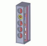
Compatible: 40 Watt Transconductance "Current Amplifier"
This is the Elsinore Project - it is DIY and uses five drivers and crossovers etc, and yet can be "current" driven.
.
This is the Elsinore Project - it is DIY and uses five drivers and crossovers etc, and yet can be "current" driven.
.
Attachments
Last edited:
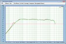
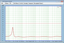
This is the Frequency Response below.
Green is "voltage" driven using a conventional amplifier.
Red is "current" driven by the 40 Watt Transconductance "Current Amplifier" of this thread.
.
Green is "voltage" driven using a conventional amplifier.
Red is "current" driven by the 40 Watt Transconductance "Current Amplifier" of this thread.
.
Attachments
Last edited:
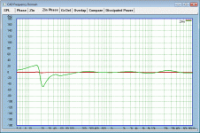
Note the Current Phase Angle:
Again:
Green is "voltage" driven using a conventional amplifier.
Red - Totally Flat is "current" driven by the 40 Watt Transconductance "Current Amplifier" of this thread.
Note that when "voltage" driven (source) Green, the current phase angle is still incredibly flat above 100 Hertz. I don't believe any commercial speaker has achieved anything like this.
.
Attachments
Last edited:
Finally the Impedance (you won't see this in any commercial speaker).
Green is "voltage" driven using a conventional amplifier.
Red is "current" driven by the 40 Watt Transconductance "Current Amplifier" of this thread.
.
Green is "voltage" driven using a conventional amplifier.
Red is "current" driven by the 40 Watt Transconductance "Current Amplifier" of this thread.
.
Attachments
Last edited:
Summing Up:
Note in the Frequency Response(s) that even the Crossover is capable of tracking correctly, whether "voltage" or "current" source driven. The Elsinore Project makes use of "Current Mirrors" that is part of the key.
If any is in Sydney, Australia, or visiting this part of the world, I can demonstrate the above speakers driven by the 40 Watt transcondctance/current amplifier described as the basis of this thread.
May I say, it sounds nothing like you average Gainclone amplifiers based on the same LM3875, in fact it makes Gainclone amplfiers (and I have built quite a few of those, probably more than anybody on diyaudio.com) sound average... very average.
Cheers, Joe
.
Last edited:
- Home
- Amplifiers
- Chip Amps
- Joe Rasmussen "Trans-Amp" - 40 Watt Transconductance "Current Amplifier"