my fault, gain is - R load/0.25+1
approximately 33 for 8 ohm and 17 for 4 ohm, real gain will depend of exactly speaker impedance.
approximately 33 for 8 ohm and 17 for 4 ohm, real gain will depend of exactly speaker impedance.
Not sure where your +1 comes from. The gain is simply Rload / Rshunt. For a real raw speaker without any impedance smoothing, the gain is all over the map.my fault, gain is - R load/0.25+1
approximately 33 for 8 ohm and 17 for 4 ohm, real gain will depend of exactly speaker impedance.
so what happens if you use this amp
to push a sealed woofer below resonance?
boom-poof?
(no offense, just thinking about using it to biamp a sealed 2-way,
maybe the obvious is to build the amp and try it out on a $20 woofer glued with construction adhesive to the top of a paint can, and invite the neighbor kids for the "big test"?)
of course, their parents would appreciate it if I had an idea of what was to be expected...
Below resonance the impedance drops so the gain drops. Maximum gain and maximum boom will be at Fc the resonance of the speaker in the box.so what happens if you use this amp
to push a sealed woofer below resonance?
boom-poof?
(no offense, just thinking about using it to biamp a sealed 2-way,
maybe the obvious is to build the amp and try it out on a $20 woofer glued with construction adhesive to the top of a paint can, and invite the neighbor kids for the "big test"?)
of course, their parents would appreciate it if I had an idea of what was to be expected...
Sealed box systems behave well below Fc. Bag End drives their speakers extremely hard below Fc on purpose.
If you want to destroy the woofer in a sealed box, use a double integrator like Bag End does. I built a point to point wire prototype and it does flatten the response between DC and Fc.
Not sure where your +1 comes from. The gain is simply Rload / Rshunt. For a real raw speaker without any impedance smoothing, the gain is all over the map.
Non inverting opamp gain formula is Rf/Rg+1.
Rload in this case act like Rf
Non inverting opamp gain formula is Rf/Rg+1.
Rload in this case act like Rf
For a non-inverting voltage amp opamp configuration, the output voltage is the voltage across R1 plus the voltage across R2.
An externally hosted image should be here but it was not working when we last tested it.
For the current drive opamp configuration, The output is voltage across R1.
I have transformers with 24V secondaries. Good enough?
Should work just fine. Barely measurably lower power, that's all.
adason circuit breadboarded
Hi all
I've been very interested in this thread as the whole constant current thing makes a lot of sense although I'm used to using it in stepper motor drivers🙂
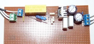
As I had all the bits to hand, I've built up adason's version of the circuit. The only change is that I used a pair of 0.15ohm resistors as the R7 to give 0.3ohm.
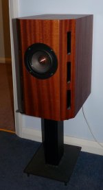
It worked first time into a dummy load so I then wired it into one of my CSS FR125 based minOnkens. The DC offset with 50 ohm across the input terminals is just 33mV. Absolutely no background hum or other noise and loads of power. The tiny heatsink gets hot but not over-the-top at normal listening levels
Power supply is a 12-0-12 100VA toroid with 20,000uF on each rail giving 34V across VEE-VCC on the chip.
It really is remarkably good even given the veroboard construction. My memory of valve amps is very old but is certainly seems to have a very open "big room" sound.
The only change I need to make is to reduce the gain a bit. Did we get a conclusion on the best way to do this? Once I properly understand this I'll make a second channel.
Thanks to Joe and adason for prompting a fun couple of hours of experimentation.
I'm very interested to get Dave's (planet10) view of using a constant current amp for the minOnken.
Peter
Hi all
I've been very interested in this thread as the whole constant current thing makes a lot of sense although I'm used to using it in stepper motor drivers🙂
As I had all the bits to hand, I've built up adason's version of the circuit. The only change is that I used a pair of 0.15ohm resistors as the R7 to give 0.3ohm.
It worked first time into a dummy load so I then wired it into one of my CSS FR125 based minOnkens. The DC offset with 50 ohm across the input terminals is just 33mV. Absolutely no background hum or other noise and loads of power. The tiny heatsink gets hot but not over-the-top at normal listening levels
Power supply is a 12-0-12 100VA toroid with 20,000uF on each rail giving 34V across VEE-VCC on the chip.
It really is remarkably good even given the veroboard construction. My memory of valve amps is very old but is certainly seems to have a very open "big room" sound.
The only change I need to make is to reduce the gain a bit. Did we get a conclusion on the best way to do this? Once I properly understand this I'll make a second channel.
Thanks to Joe and adason for prompting a fun couple of hours of experimentation.
I'm very interested to get Dave's (planet10) view of using a constant current amp for the minOnken.
Peter
Attachments
Last edited:
I'm very interested to get Dave's (planet10) view of using a constant current amp for the minOnken.
Peter.
Have you added damping to the vents?
dave
Dave
Built as per the original "free" plan set using whatever acoustic wadding was specified then
rgds
Peter
Built as per the original "free" plan set using whatever acoustic wadding was specified then
rgds
Peter

but that heatsink is too small...
Yes it was just to give a first try.
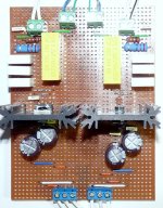
I've now built a dual mono version with proper heatsinks. I've also increased the load resistor to 0.45ohm by adding a 3rd 0.15ohm resistor to reduce the gain a bit.
I did try building it single supply stereo - DON'T BOTHER!! heed Joe's warning.
This version is running on a pair of 12-0-12 100VA transformers, full wave rectified with 10,000uF on each rail.
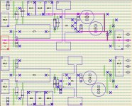
Despite being breadboarded it is running completely stably and has a great sound. A slightly modified breadboard layout is attached. I run a solder bead along all the tracks covering all spare holes to increase current carrying capacity and break all tracks to keep them as short as possible. There may be some small improvement by laying it out on a PCB but it is certainly very acceptable as-is.
It will replace a Tripath TP2050 amp I've been using in my workshop driving the miniOnkens and there is no comparison in the quality of the sound; the LM1875s in this configuration blow the Tripath away.
Attachments
Despite being breadboarded it is running completely stably and has a great sound. A slightly modified breadboard layout is attached... and there is no comparison in the quality of the sound; the LM1875s in this configuration blow the Tripath away.
Sounds like you are having fun. 🙂
As for audio amplifiers, there was never a better review than that.. . . seems to have a very open "big room" sound.. . .
As for audio amplifiers, there was never a better review than that.
As good as any I have heard too. 😀
.
I've been auditioning all sorts of music and I have one problem. The constant current drive is creating a huge increase in volume around Fs. Looking at the impedance plot of my speakers http://meniscusaudio.com/images/CSS-FR125-data-v3s.pdf you can see the impedance increasing dramatically at Fs. Now obviously the gain of the amp is also increasing with the ratio of impedance/load resistor and this appears to be significantly overcompensating for the drop off in response of the speakers.
Can anyone suggest a way of taming this?
Peter
Can anyone suggest a way of taming this?
Peter
UPDATE:
I tried putting 20ohm across the speakers to limit the effective impedance. This worked to tame the excessive bass but seemed to impact sound quality.
The next test was to change R2 on adason's circuit from 22K to 1K5 effectively putting a high pass filter on the input with a corner frequency of 48.3Hz. This seems to give a much better result. I can probably go a bit lower on the resistor (1K2) but will run it as is for a bit with different music to gauge better the impact.
Installing the standard feedback configuration (see datasheet) or you could cheat and try to flatten the speaker impedance curve but that would make using a current amp a bit pointless.
UPDATE:
I tried putting 20ohm across the speakers to limit the effective impedance...
This effectively makes the output Z of the amp 20 Ohm. That is 20 Ohm is effectively in parallel with the 200+ Ohm output Z of the amp. Basically a current output amplifier approximates a voltage source (0 Ohm) with a large value series resistor, that is why the 20 Ohm now will look like it in parallel with the existing output Z. One side of each value 'resistor' sees 0 Ohm. Takes a bit of lateral thinking, but it is true.
Cheers, Joe
.
- Home
- Amplifiers
- Chip Amps
- Joe Rasmussen "Trans-Amp" - 40 Watt Transconductance "Current Amplifier"