Hi Joe,
Will you recommanded not to use wire wound resistor for 0R33 due to inductance ?
Is thick film or carbon film ok for this ?
"Note the Resistor 0R33 - I used three 1 Ohm Resistors in parallel. These must be low inductance and the 6.5W rating is minimum."
Thanks
Will you recommanded not to use wire wound resistor for 0R33 due to inductance ?
Is thick film or carbon film ok for this ?
"Note the Resistor 0R33 - I used three 1 Ohm Resistors in parallel. These must be low inductance and the 6.5W rating is minimum."
Thanks
Hi Joe,
Will you recommanded not to use wire wound resistor for 0R33 due to inductance ?
Generally the inductance would be low, even with wire wound, at that low Ohm value. If memory of the top of my head serve me right, I used three 1 Ohm Dale CW-5 wire-wound resistors in parallel - being in parallel reduces inductance. Note too the schematic, that 4K7 and 1n5 on the input is a low pass filter to prevent slew rate, the roll-off is much more than the very slightest inductance still remaining. So yes, I don't think using a good quality wire wound is going to cause any problem.
Cheers, Joe
.
Hi Joe,
Please, any comments on this? I have some LM1875 in my draw. Shall I try this? Your comments highly appreciated
Yes, they should work nicely, just scale down the power supply and all that will be different is the less power to the speakers.
.
Why are there two feedback paths in each half of the amplifier?Hi Joe,
Please, any comments on this? I have some LM1875 in my draw. Shall I try this? Your comments highly appreciated
Why are the two feedback paths set to the same values?
Hi Joe,
Please, any comments on this? I have some LM1875 in my draw. Shall I try this? Your comments highly appreciated
Hang-on, - I was under impression that you wanted to use some LM1875 for the original schematic I posted in #1 .
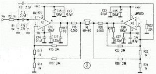
The schematic you posted in #83, I cannot vouch for as I have not built it. I note that it is a bridged version and that the "-" (inverting) input has an effective 2K input impedance and would be hard to drive - certain not a tube preamp.
Where is this schematic from and what is supposed to drive it? It is like having an incomplete picture.
Cheers, Joe
.
Why are there two feedback paths in each half of the amplifier?
Why are the two feedback paths set to the same values?
If you are referring to the schematic in #83, it is bridged - this doubles voltage swing with a lower rail voltage power supply.
.
Hi Joe,
you are right, it looks like the input impedance is too low for my tube preamp. I actually got this circuit from the site below. Any way I will try your single ended version. Many thanks
Free Electronic Circuits & 8085 projects Blog Archive LM1875 based BTL application experiments and current-feedback design circuit Free Electronic Circuits & 8085 projects
the bridged arrangement has two halves.If you are referring to the schematic in #83, it is bridged - this doubles voltage swing with a lower rail voltage power supply.
.
Each half has two feedback paths. Both of these feedback paths have the same values.
Why and why?
first time i've seen such a feedback arrangement..
i can only hazard a guess, that the 0.39 resistor is being monitored for current,
any tendency to run big currents decreases gain, how effective this is, i don't know..
i can only hazard a guess, that the 0.39 resistor is being monitored for current,
any tendency to run big currents decreases gain, how effective this is, i don't know..
Post 83 looks like it is arranged for low voltage use, such as when using a 12+12vac transformer at the power supply and getting 26W into a heatsink as well as 26W to an 8 ohm speaker from your bridge amp. At that voltage (about 17vdc rails), the LM1875's speaker output wattage is very similar despite load variance.
It is a current drive amplifier, so it could be used for guitar amp, old style classic design of full range driver (and other speakers made for correct response with tube amplifier's output transformers) and for more bass extension with ordinary sealed box speakers.
However, duplicated feedback loops isn't required for current drive amp, so there's an extra function of some sort??
Last edited:
A (stupid?) question: can be made the same with a opamp? As example in a headphones amp as a Cmoy?
If the answer is yes, please, can post a schematic? If possible with a 4556 (or any other), is a high current opamp good for headphones amp, and I have two.
Anticipated thanks
If the answer is yes, please, can post a schematic? If possible with a 4556 (or any other), is a high current opamp good for headphones amp, and I have two.
Anticipated thanks
For the 4556 headphone amp, this sort seems possible:
Lenard Audio's schematic, variable current drive.
Ideal component values are probably different (not shown) for 4556, but the method looks good
It doesn't feature much automatic tracking, but it does have a manual dial to match up speakers (or headphones) approximately.
Given the headphone's 3 wire hookup, at worst you'd just get a very little bit of "don't do what I do" causing a tiny amount of stereo broadening, which may actually be desirable for headphones anyway. I see a few differences, but what I don't see is a problem.
Last edited:
SO THIS AMPLIFIER CAN DAMAGE THE WRONG SPEAKERS!
Also, the Crossover (High Pass) to the Tweeter could also damage it in a very short time.
Yes, the use of Current Output Amplifiers are suitable for Full Range Drivers and also speaker systems that are designed to work with current.
Hi Joe,
How do I find out if the speaker was designed to work with current? Anyway to test it? I am using a pair of Aristoteles Horning and like to try the Current Amplifier if it is safe. I was told that this spearker sound best with low power tube amp.
Thanks
I am using a pair of Aristoteles Horning and like to try the Current Amplifier if it is safe...
Truth is that I can't tell you. Just don't know enough about the speakers to say.
.
Hi Joe
This is a quote form an old link.
It show's (for me anyway) a very effective way to use a current amplifier.
There seem to be 2 major issues with implementing this type of drive
1, the possible reaction with a passive crossover.
2, the reaction of the driver at Fs.
Both of these issues seem to be dealt with in this quote.
my summary being.
Do not use passive crossovers.
Operate the driver well above Fs.
My own system uses a Goodmans 201 ( 12" full range) in a 450mm wide open baffle ( width due to WAF )
With a 15" driver mounted below
Each driver has it's own amplifier which is fed from a minidsp which is used for crossover and room correction
The crossover point is 230Hz
I am going to try Joe's Trans-Amp on the full range as this seems to be a safe place to implement this style of amplifier
Comments?
Mark
Konnichiwa,
Quote:
Originally posted by janneman
-give less nonlinear distortion.
Why?
Isn't it obvious?
You have a coil filled with solid Iron. Eddy losses give rise to a cubic distortion with applied voltage, for voltage feed, as the current is distorted. Current Feed, no distortion (from this source).
Quote:
Originally posted by janneman
-eliminate the effect of Lvc.
What about the xover filter? The Lvc is part of that. Again, all bets on the result are off.
Well, I believe current feed is applicable ONLY for active speakers (or fullrange), but again, this should be obvious.
Quote:
Originally posted by janneman
-completely eliminate VC - heatup releted SPL loss.
Correct. Is this significant enough in hi-fi apps to warrant a complete strategic redesign of the whole system?
ABSOLUTELY.
One UK studio mag tested a number of "HiFi" and "Studio" monitor designs of the classic "small 2-Way" (aka LS3/5 & grown up company). They found at rated input power 5 - 6db compression and 10 - 20% distortion (3rd harmonics - eddy current created) in the midband for the socalled "HiFi" Speakers.
In fact, if we sit down and instead of slavishly copying again and again the same fundamental mistakes made by virtually ALL Designers of HiFi Gear (such as passive crossover speakers in reflex enclosures, with **** poor radiation pattern control and riddeled with high distortion and severe compression due to a voltage interface), we can actually sit down and design a system that ACTUALLY works.
May I propose a few ideas?
A lot of what ME Gaithein does makes eminent sense. They use a "pseudo coaxial" driver with a modest "open baffle" fitted with a 5.25" Midrange and 1" Tweeter, mounted in front of a 15" Woofer.
How about using as driver the Seas 6.5" Coaxial with the XP Cone, on a modestly wide open baffle and driven via current drive (both tweeter dome and lf cone)? With a Qm of around 1.3 and an Fs around 40Hz this will do nicely as extended midrange driver with co-incident tweeter on an open baffle.
Also, the combination of open baffle and hornloading the tweeter with the cone produced an excellent dispersion control (the exact opposite of the stupid "wide dispersion" designs so commonly turned out by Idiots as "HiFi" speakers).
Depending upon the exact baffle size the crossover between cone and large "woofer" would likely fall between 250-500Hz if we used the semi-coaxial but can probably be pushed down to 125Hz with a suitable width baffle (~ 20" wide). At such a low frequency we can place the 15" Woofer below the main driver.
The woofer now could be a dipole or a "cardiod" system with suitable flow resistances (or by adding a 15" dipole and a modest size monopole woofer) and again use a low Qm driver with current feed. If a low Qm driver is not available off shelf we make one by packing the area directly behind teh driver with a "flow resistance", lowering Qm untill we can use current drive.
Now the resultant system should play loud without strain, distortion or compression, work well in normal small rooms and do all of this for a quite piddly budget, compared to many "Super High End" projects.
Sayonara
Hi Joe,
there is max 60DC of the power supply in 1875's datasheet,
you are using +- 35=70V
did the chip survived?
was the radiator very hot?
there is max 60DC of the power supply in 1875's datasheet,
you are using +- 35=70V
did the chip survived?
was the radiator very hot?
- Home
- Amplifiers
- Chip Amps
- Joe Rasmussen "Trans-Amp" - 40 Watt Transconductance "Current Amplifier"