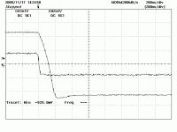
As promised, I looked at the line amp square wave response with 6ft of cable terminated by a 10k resistor. The cable caused a small increase in output undershoot. I have some nice IMB 270 pF polystyrene wrap and fill caps at home, so I tried the equivalent amount of capacitance as compensation, and the response is nice and slightly overdamped, the way I like to see it.
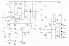
Attached is a schematic representing the current state of affairs. For anyone trying to duplicate this circuit, Q2, Q4, Q14, Q17, and Q19 have source resistors selected for the proper value of drain current (10mA for Q2, Q14, and Q19, 1 mA for Q17, and 5mA for Q4. These values will need to be different depending on the FETs you have on hand. Q3 and Q20 were selected for Vgs > 5V at 2mA drain current. Q1 and Q18 were matched for Vgs at 10 mA draiin current. Q5 and Q6 were matched for Vgs at 2 mA drain current.
I'm installing the new compensation caps tomorrow, then I'll try loading it into my living room system for some listening tests.
Attachments
I had a little extra time today, and simulated a bipolar cascode with the base circuit referenced to the summing node. THD is slightly better than with the PN4391 JFET cascode - 0.0041% vs 0.0044% or thereabouts. Distribution of harmonics is about the same, with the overall levels on each harmonic in the JFET cascode just a little bit higher. This says nice things about the PN4391. I may try the bipolar cascode down the road, but I will have to use a clean current or a heavily filtered split resistor to drive the base so that I'm not injecting any nasties directly into the summing node.
The completed lineamp board is currently sitting on a shelf in my living room waiting its turn to be installed. It'll probably be behind the mods I'm planning for my newish P-P tube amp - check my "Kingfisher" thread for details on that one.
The completed lineamp board is currently sitting on a shelf in my living room waiting its turn to be installed. It'll probably be behind the mods I'm planning for my newish P-P tube amp - check my "Kingfisher" thread for details on that one.
i am really interested how your modern liniac sounds so please fire it up and tell us how it sounds. i have not seen such an interesting single ended circuit for a while. i usually do parrallel symmetric and i can remember quite firce discussions we had 25 years ago about the merrits of the two aproaches.
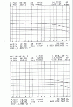
I finally got this line amp into a box with an RIAA preamp along side it, with the intention of bringing it to this year's Burning Amp. Fate intervened, and I'm still working on the preamp box. Here's the response curves for the "Liniac-Like" lineamp. Tonight I get to hear how it sounds (maybe).
Attachments
This line amp, combined with a nice California Audio Labs Ikon MkII CD player, is letting me hear everything whether I like it or not, including rustling pages, violinists picking up their bows, and traffic outside the concert hall. The recording is Neville Marriner and The Academy of St. Martin in the Fields, performing Vivaldi's "Four Seasons". The Decca reissue of this recording on CD is pretty nicely done, and I just picked up what I hope is a fresher copy of the vinyl release, which originally came out on Argo.
My overall impressions of this circuit are still very positive. The extra 5X gain (replacing a follower line amp) helps to squeeze the utmost out of my components. Resolution of detail is exquisite. What also helped was subbing my old speakers back into my setup, which with the 1.5k crossover frequency imposed by my new jfet active crossover, are now very smooth and detailed at high volume. The speakers used a 5 kHz crossover frequency in the past, which did not sound anywhere near as good.
The Tri-Trix speakers I used in place of my old speakers for a while are very harsh (painful, really) in comparison. The old speakers are now going to get some loving detail and attention so that they look as good as they now sound. I'm scratching my head as to what to do to alleviate the harshness of the tri-trix speakers.
With these results as impetus, I'm going to try to adapt this approach to a vacuum-state line amp.
My recollection of the Liniac is that it was a two device circuit, with shunt feedback. I remember building and testing one back in the 70s and it was awful. Terrible distortion figures.
Sent from my HTC Desire using Tapatalk
Sent from my HTC Desire using Tapatalk
Well, this version simulates very nicely, if you check the thread, and sounds great. It's not a straight Liniac, as already pointed out by a pundit, but inspired by the original circuit. It's the first line discrete amp with gain I've built that I've liked. The first one I tried got ripped out after about an hour of listening. Gain of ~one is easy. Gain of 50 - not too hard. Gain of five - another story.
Hi Wrenchone
A long time in the finishing but well worth it, I imagine.
This is relatively complex and unusual stuff for many of us. Would you care to note any special requirements of components selected, operation and perhaps some PCB details if you feel they are relevant to anyone wanting to emulate your good work. I think you might have Joachim in there, at least.
It's not all that complex - you're seeing both channels plus the regulator in the schematic. When I get some time, I'll talk about what's going on and dissect the thing into its functional blocks.
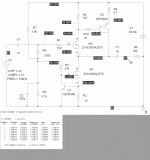
This is the basic skeleton of the "Liniac Inspired" (try to quibble with that) line amp. This satisfies several requirements I set forth 1) single-ended 2) single supply 3) non-inverting 4)output quiescent point is fairly close to 1/2 Vcc for good signal swing 5) gain between 5 and 10. It turns out that it's fairly difficult to satisfy these requirements without something that looks a lot like an opamp. It's easy to do with an opamp, but that's not the point of this exercise. Other attempts I made at a line amp with gain got abandoned quickly because that didn't sound so nice, so I've been getting by with unity gain buffers of various types until now. This is actually a variation on a unity gain buffer circuit I've been using that has 100% feedback - more on that later.
The main gain element in the circuit (the boss, as it were) is jfet Q5. jfet Q4 cascodes Q5 and pins its drain at a relatively constant voltage. So far, this is like a common source amp with cascode. Q5 drives PNP darlington transistor Q3, which is fed back to the source of Q5. Originally, I used a circuit like this as a unity gain buffer, so that the drain of Q3 was fed directly back to the source of Q3 with no intervening resistor. Small changes in the Q5 drain current get fed directly back to the Q1 source, in effect multiplying the effective transconductance of Q5 many times. This results in a really good buffer, especially when Q1 source resistor (R10) is replaced by a current sink. At any rate, I've used a circuit based on this principle for a unity gain line amp for quite a while, but I wanted something with a bit of gain.
Back to the chase - the inspiration I got looking at Hood's Liniac circuits was to replace resistive loading at the Q4 drain with a current source. Now any changes in the drain current of Q1/Q4 are resisted by Q2, so that any changes, no matter how minute, are shoved directly into Darlington Q3, where they are multiplied tremendously (a good Darlington has huge current gain) and fed back to Q5. Resistors R8 and R10 set the gain of the circuit. Current source I1 provides additional bias current to Q5 that is not directly in the gain path, boosting the transconductance of Q5 and reducing distortion. Biasing Q5 with a current not directly in the gain path allows it to be cascoded with a simple jfet, as only a small portion of the total drain current of Q5 (~ 1/6 in the actual circuit) is flowing in cascode fet Q4. An asymmetric current mirror(R1-2, Q1-2) provides a scaled-down portion of current I1 to the drain of Q4, and acts as load for Q4. Resistors R4, R6, and R7 act as stoppers. C3 is a compensation capacitor. R11 grounds the other side of output coupling capacitor C2
Attachments
Attached is an example of the buffer circuit I mentioned. This was used as a unity gain buffer block in a fet active crossover. The board is on the bench awaiting a few mods (some protection diodes for the input fet gates and a change in crossover frequency) before I put it in my living room system.
Attachments
post34
I don't need >1.7Mpixels for that schematic.
Surely no one else does either.
Squeeze it a bit (or a lot) so that it fits our screens.
post33 <266kpixels and <8kB
I don't need >1.7Mpixels for that schematic.
Surely no one else does either.
Squeeze it a bit (or a lot) so that it fits our screens.
post33 <266kpixels and <8kB
Last edited:
Don't know how that happened, as the schematic was saved as a *.gif and didn't weigh in as more than a few kB when I uploaded it last night. I'll look into it tonight when I get home, except that now it's too late for anyone but a moderator to fix.
I don't get it either, I only have a thumbnail blowing out to 575 x 540 px. Similar size to that in post #33. Browser issue?
Get a better browser Andrew.
post34
I don't need >1.7Mpixels for that schematic.
Surely no one else does either.
Squeeze it a bit (or a lot) so that it fits our screens.
post33 <266kpixels and <8kB
The file I uploaded last night was a 46k *.gif file. It displays fine here at home on Seamonkey, lousy at work on Internet Exploder. It may be just an issue of display setting, as I have a 24" monitor here with 1200 X1900 pixels, and less resolution at work. The pics can also be viewed in posts 52 and 53 of my "JFET Active Crossover" thread where they were originally posted. Anyway, that's the simpler follower edition of the circuit. I used somewhat different parts to actually build the follower, but the concept remains the same. I was going to dump that crossover board in the same box as my other preamp modules, but I may give it a box of its own so I can mix and match crossovers later. The speakers I have currently in the living room fare best with a 1.5k crossover frequency, but the next pair using an MTM setup with Tang Band 4" "full range" drivers may likely fare better with a 5k crossover frequency.
what suggestions do you have?Get a better browser
I started out with IE and quite a while ago moved to FF.
But, I don't think 1.7Mpixels is a Browser issue.
It's a poster issue.
I can't see 1.7Mpixels on my screen.
- Status
- Not open for further replies.
- Home
- Source & Line
- Analog Line Level
- JLH Liniac Revisited


