Attached is a variant of Hood's Liniac circuit from the 70's with some bells and whistles thrown in. The intended application is a line amp with gain. The perfect current source in the simulation schematic will be replaced with a JFET current source. The current source is there to supply extra bias current to the input JFET J1 such that the current it swings to push the output around is a small proportion of the total bias current. The current mirror (Q3, Q4) provides a low-headroom 2 mA current source as load for J1. J2 is a cascode for J1, doing the usual cascode things but also clamping the drain voltage of J1 to a reasonably low value, allowing healthy bias current without undue power dissipation.
I'll be building this up soon, as the simulation is one thing, but the listening experience is quite another.
I'll be building this up soon, as the simulation is one thing, but the listening experience is quite another.
Attachments
I like a JFET because it floats on top pf the input JFET source without requiring any external drive voltage. I may consider using a depletion mode MOSFET if I can find something suitable. I have some lower voltage Supertex parts I may try, at least a far as having a look at them in my sorting jig to see what the VGS is at 2 mA.
i tried the fet-fet cascode and the fet-bipolar performed better for me but i understand your resoning it is such an elegant oportunity
If I did a bipolar cascode, I would drive the base of the bipolar referenced to ground rather than the J1 source so as not to inject extra current into the J1 source resistor/summing node. Not really a cascode after that, though it still satisfies most of the purposes for having it there in this circuit.
As an extra comment on the bipolar-fet vs. fet-fet cascode, I take pains to select the cascode fet such that there is enough VGS at the bias current of the lower fet to tone down the parasitic capacitances. I like to see 4-5V across the bottom fet. I don't know if other designers have taken this into account when making a comparison.
Having said that, I realize that a bipolar in general will may pin the drain voltage of the bottom fet much more securely than an average jfet, as the current pumped through the base-emitter voltage of the bipolar (the difference in base current due to the change in emitter current) will cause a much lower shift in the bottom fet drain voltage (assuming decent gain and base spreading resistance) than in the case of the fet cascode element, where the VGS of the top fet must change to accommodate the signal current in the bottom fet. If the cascode fet has low transconductance, the VGS modulation may be significant.
Food for thought, anyway.
excellent explanation, i could not do it better. The Paris-Aksa head amp has the base of the cascode bipolar referenced to ground and it works surprisingly well. -143dB noise with only one high gm fet. distortion is mostly second harmonic in single ended topology.
Just for grins. I subbed in a BJT cascode device (a 2N4401, no slouch) referred to ground in place of the floating JFET cascode. It's still early days yet, but the substitution caused a 2X increase in THD (didn't look closely at the harmonic distribution, will putter around more with it later). One explanation for this may be that this is a very low gain amp, so the summing node moves around. Next time I look at the sim, I'll plant a probe there.
For information, in what situation did you see better results with the BJT cascode as compared to a JFET cascode, and were the conclusions based on measurements or listening or both? I'm not getting argumentative here just wanting to know the facts in your case.
For the simple single-ended, single supply circuits I'm investigating, reasonably high gain and unity gain (or thereabouts) circuits are simple - low gains (<10) are a bitch.
i look at it from the impedance standpoint. most bipolars have lower impedance at the emitter than comparable fets at the source. the result is more speed and lower distortion.
maybe the gm of your fet is high enough so that is not the problem.
actually i build a fet-fet cascode mc pre-pre (it was more like SRPP) but was not very impressed by the performane. it worked but it did not put a lasting impression in my mind. what i have and sometimes listen to is a fet-bipolar cascode mc pre-pre.
it sounds good, very transparent and open. nothing of the fat and worm sound that people atribute to fets because they behave like tubes. the bipolar specimen in that design is a 2N4401 too, funny
Circuit, please- I want to compare operating scenarios. What is good in one situation may nor be so good in another, usw... I'm building up the circuit I simulated (with some component differences) and intend to sub it into my living room test bed. So far, the discrete single-ended lineamps with gain I've tried have been less than satisfying from a listening standpoint. I'd like to break that particular jinx.
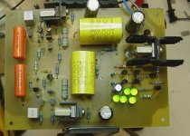
My Liniac is almost built. A couple more solder joints and I can start bringing it up. It has an on-board high speed shunt regulator.
Hey Wrenchome,
I´m sure your circuit OK. But where is the Liniac topology🙄?? The Liniac was a inverting one-stage configuration with FET-CCS and emitterfollower. I built it -71 when it was presented and liked it. Hadn´t so much to compare with though😉.
Changing the BJT to a cascoded JFET is not a bad idea. But changing the emitterfollower to a gainstage makes it not being a Liniac anymore. Below is the original article.
http://anacon-tech.com/IPdocs/JLH_LINIAC.pdf
It's not strictly a liniac, but one of the direct variants he came up with. I got the bare bones of the circuit out of the Paul Kemble compendium of Hood circuits at A Paul Kemble web page - John Linsley Hood preamp designs. . If you want to be a stickler about it, I could call it a "Hood Feedback Pair", but the Liniac was definitely its father.
Puppy is up and running after fixing some bonehead stuffing errors. Some compensation is required for optimal square wave response. Without compensation, there is damped undershoot with 10kHz square wave excitation. A 220 pF compensation cap clears this right up. Either I'll settle for an NPO cap, or go scrabbling around in my assorted polystyrenes for something that will do the trick. I also want to try driving a 6ft output cable terminated by a 10k resistor to see if a modest amount of capacitance can be tolerated without the electronic equivalent of a hissy fit...
I might be a stickler about the nomenclature but the only thing in common with the Liniac is that it was last in the same article😉. Think Kemble mentioned that to.
The nice thing about the Liniac was that it only had one gainstage making it act like a triode when feedbacked. Lets leave it by that. Have you vere tried the JLH 10W? It was the first transistor amp I built back in -69 and I still remember the sweet sound of it.
You HF problems might be due to the high gain of the two cascaded gainstages. Hope you fix it and that it sounds!
Anyway whatever you call it, here is its respose to square wave excitation. The smaller waveform is the input, the larger in amplitude is the output. The leading edge is well-behaved. Remember that this is a single-ended amp so that the leading and trailing edges will have different slew rates. Also, since this is a feedback system, a little bit of high frequency compensation is not at all unheard of. I'm using 130 pF, which leaves the trailing edge a tiny bit undercompensated, but it's something I can live with for the time being. I want to see what it looks like driving a 6ft output cable before I make any final decisions on compensation.
Attachments
- Status
- Not open for further replies.
- Home
- Source & Line
- Analog Line Level
- JLH Liniac Revisited