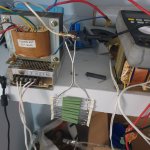
Hi. There is 2 different primary because it is connected to 220-230v input when charging battery and 250v one is for elecrricity outage and it drops about 10% when feeding the line. I already connect it to 220v one. I will measure ripple tomorrow.
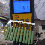
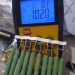
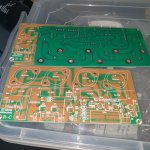
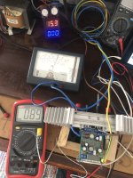
I could not connect Filter right now ,transformer cables are too thick to fit pcb, but i made 1R 100w resistor with Vishay AC 10 NI non inductive 10R resistors. Here is approx results with no load and after connecting test resistor. Red is common cable.
Red white cables 8.10v to 7.72v
Red blue cables 8.08v to 7.64v
Blue white cables 16.12v to 14.52v
Red white cables 8.10v to 7.72v
Red blue cables 8.08v to 7.64v
Blue white cables 16.12v to 14.52v
Attachments
Last edited:
If I understand your results you are seeing less than 0.5V drop for 7A load. Is that right?
If the transformer is 114x40mm it should be something in the region of 150W so at 16V output that seems right for approx. 8-9A. That should be plenty to run a JLH for 4 ohms and you might be able to get 10W from it, per channel, but you would need high current low voltage drop rectifiers and large reservoir capacitors.
If the transformer is 114x40mm it should be something in the region of 150W so at 16V output that seems right for approx. 8-9A. That should be plenty to run a JLH for 4 ohms and you might be able to get 10W from it, per channel, but you would need high current low voltage drop rectifiers and large reservoir capacitors.
Hi.Yes.I can supply low voltage drop diodes and big capacitors easily. Which circuit should i build? I can not find a schematic for my application.
Well, I don't know either.
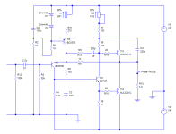
But a first pass simulation would be along the lines of the circuit I've attached. It has the 1996 input current source (modified to use diodes instead of a transistor limiter) but a bootstrap driver to maintain high efficiency.
As regards the choice of output transistors, it's not obvious at the moment. For best HF response the modern devices are winners, but people report stability problems with them. Also, modern devices tend to have quasi-saturation effects which reduces the gain at low colelctor voltages and higher currents. I would suggest some of the older but higher frequency devices like the 2N5882 perhaps, which have lots of current and maintain a high gain at relatively low voltages, but the HF response won't be so good.
And because the supply voltages are low, we're struggling to obtain low distortion at low impedance loads near clipping. So, I have reduced the feedback resistor and grounding resistor to reduce the distortion a little. It simulates at .07% at 7W into 3.9 ohms. If your PSU gives you 11V that will help.
To aid with stability I've included a 220pF phase lead capacitor and base stopper resistors in the MJL's.
Caveat and warnings- not optimised, not built, not tested, and the bias resistor pots may need some playing around with.
If anyone wants to chime in please do so.
Attachments

For alternative power transistors to the Sanken and Onsemi front runners, I now use some of the common Chinese versions of 2SD1047 because they're very cheap for TO3P audio grade semis and linear but not excessively fast, since there's no benefit from extreme fT in class A. There are many competing sellers and a number of manufacturers, including ST micro and other well known producers, with genuine KEC product probably the best, if you can find and identify it. The Sanyo originals were the type universally fitted to all the highly regarded discrete Rotel models in the 1990s but I wouldn't expect all copies to be as good in class AB. Unfortunately, some products will be trash too. That seems to be how platform selling and sellers are - YMMV.
2SD1047 and complement 2SB817 are generally considered as triple diffused planar types, like most affordable audio power semis now, though somewhat slower than 2SC5200/2SA1943, for example. I only assume they will be slow enough to eliminate problems with instability though, as I haven't had a problem using them in my own JLH tinkering. https://datasheetspdf.com/datasheet/2SD1047.html https://datasheetspdf.com/pdf-file/70747/SanyoSemiconDevice/2SB817/1
2SD1047 and complement 2SB817 are generally considered as triple diffused planar types, like most affordable audio power semis now, though somewhat slower than 2SC5200/2SA1943, for example. I only assume they will be slow enough to eliminate problems with instability though, as I haven't had a problem using them in my own JLH tinkering. https://datasheetspdf.com/datasheet/2SD1047.html https://datasheetspdf.com/pdf-file/70747/SanyoSemiconDevice/2SB817/1
Last edited:
Ian, your suggestion of the 2SD1047 looks interesting. It seems to be quite fast ("only") 20MHz compared with 2SC5200 (30MHz) (typicals) but shows slight quasi-saturation at about 2V and 4A, but that should be OK for a low voltage lower power load even into 4 ohms.
In JLH's I have built with 2SC5200's and MJL3281A's, one needed a 33pF compensation capacitor, the other not. With increased feedback for low resistance loads to keep the distortion low, I suspect that the scheme I showed in the post above would be better, but to note that the base stopper resistors may need to change depending on the output transistors used. The problem with these is that they will clip the negative output voltage if too high.
I don't see that Class A means that you can accept lower frequency transistors. They still need to be driven or respond to high audio frequencies as fast as a Class (A)B amplifier. Buried earlier in this thread is a comparison of rise times using the original RCA-2N3055 (last known as 2N3055H), an epi device (2N3716) and MJL3281A. The JLH needs fast transistors as there are no drivers to push or pull base current to speed them up, so if anything, the JLH needs faster devices than in a Class AB with drivers.
Thank you John, I appreciate your comments and suggestions on compensation and I'm also interested in what others may have reported on stability too. When I mentioned extreme fT though, I was thinking of 2SC2837 with its 70Mhz fT spec. as opposed to MJ480 or 2n3055's 4MHz. 2SC2837 may not be a likely candidate for a JLH build and I haven't tried any in JLH experiments either, but I'm wary about such output devices if we already have stability problems. The stink of burnt epoxy when you take one risk too many with plastic power, is none too pleasant either 
Last edited:
Hi. I also have pcbs jlh 2003 and 4 x 18v ac seperate output 500Va toroidal transformer too.I have 2n3773 and 2sc5200 toshiba transistors. Which Can i use them?
My friend told that jlh2003 will not work well because it does not have thermal compensation ( bias transistor not attached on heatsink) I have many options. I am confused which one to build. I am just looking for best sounding single ended class a which have 15-20w power to 4 ohm. ( i have ta2020 class d right now and happy with it but looking for better sounding amp)
My friend told that jlh2003 will not work well because it does not have thermal compensation ( bias transistor not attached on heatsink) I have many options. I am confused which one to build. I am just looking for best sounding single ended class a which have 15-20w power to 4 ohm. ( i have ta2020 class d right now and happy with it but looking for better sounding amp)
Attachments
Last edited:
I think this board is a more advanced design contributed by Tim Andrew and last updated July, 2003. It's title is very likely "JLH Class-A Update" and you can locate it at The Class A amplifier site - originally started by Geoff Moss, now an archive hosted by ESP. http://www.sound-au.com/tcaas/jlhupdate.htm
There is plenty of comment, variations and explanations of what and why changes were made as the design was developed. However, this is a work of refinement and perfection by a musician. Who knows what you will hear with the choice of components and semis that are available to you? I would be thinking carefully about the options.
There is plenty of comment, variations and explanations of what and why changes were made as the design was developed. However, this is a work of refinement and perfection by a musician. Who knows what you will hear with the choice of components and semis that are available to you? I would be thinking carefully about the options.
And don't be concerned about your friends comment regarding thermal compensation. Sensing is only necessary for class AB amplifiers. Class A amplifiers generally operate at maximum bias current continuously so there will be nothing apart from the signal that varies enough to need it but that certainly means there will be a lot of heat output from the heatsinks, regardless of the audio output.
Last edited:
Could you tell which one may sound better ? JLH2003 or Aleph J ? I also have Aleph J pcbs and most of parts
No, I don't think anyone could. They both sound great, just pick one.Could you tell which one may sound better ? JLH2003 or Aleph J ?
Then you can build the other one and compare them.
Hello Veysel,Could you tell which one may sound better ? JLH2003 or Aleph J ? I also have Aleph J pcbs and most of parts
If you would like to know how to do a proper test here is the text of Mr Hood's test, the final arbiters being him and his audio friends ears.
Regards - J
I get 18 volts DC (no load) which drops to aboutHere is transformer. It is about 3200grammes and very silent.I think it may be around 250-300w. I am not sure how many voltage drop happens.
16.3 volts which leaves me approximately 8 volts across each output transistor after losses.
I found that using two JLH69 on same transformer @ recommended level of 1.2 amps quiescent caused my voltage to drop to about 14 volts. Although the design still works !
So the UPS Transformers would be good for a single channel JLH69 Amplifier but you would need to find two the same which is unlikely. I’m amazed that I’ve found a picture of a similar UPS transformer I was testing my versions of the JLH 69 on this Thread!
I’ve also tried the dual rail version of the JLH69 on the same transformer which is hopefully illustrated in the picture I’m about to attach !
Looks as if it’s worked!
Last edited:
Hi. I think my transformer is enough for 2 channels. Yes please also try dual rail version and tell the results.
Hi Veysel,
I did notice afterwards that my UPS transformer has EL-96*40 on it & your UPS transformer reads EL-114x40 so I’m assuming these are dimensions in millimetres, Therefore the bigger the better. I agree with you that yours will be able to supply two JLH69/96 or 2003 versions as you have plenty of current available as demonstrated in your previous posts which I hadn’t initially seen ,
I was just catching up with the thread when I saw a similar transformer hence my post.
However since that post I’ve tried gradually increasing the quiescent on my JLH69 dual rail prototype to 2 A , and the voltage across both rails actually reduced to 15 volts. I am not able to get over 2 amps as it increases quickly & a hum is heard in the speaker. Besides the temperature increases to about 90 degree’s Celsius. Here are some pictures of it when the output to the speaker has been adjusted to zero with the quiescent current set to
500 mA

1 A

1.5 A

And finally 2 A

All the above are fan cooled as the heat sink was getting uncomfortably hot at high quiescent currents.
William
I did notice afterwards that my UPS transformer has EL-96*40 on it & your UPS transformer reads EL-114x40 so I’m assuming these are dimensions in millimetres, Therefore the bigger the better. I agree with you that yours will be able to supply two JLH69/96 or 2003 versions as you have plenty of current available as demonstrated in your previous posts which I hadn’t initially seen ,
I was just catching up with the thread when I saw a similar transformer hence my post.
However since that post I’ve tried gradually increasing the quiescent on my JLH69 dual rail prototype to 2 A , and the voltage across both rails actually reduced to 15 volts. I am not able to get over 2 amps as it increases quickly & a hum is heard in the speaker. Besides the temperature increases to about 90 degree’s Celsius. Here are some pictures of it when the output to the speaker has been adjusted to zero with the quiescent current set to
500 mA
1 A
1.5 A
And finally 2 A
All the above are fan cooled as the heat sink was getting uncomfortably hot at high quiescent currents.
William
Attachments
I've been fiddling about with different amplifiers for several months, and listening to them and comparing them using switched tests.
Today I listened to Lenny Bernstein's Mahler 1, halfway through the first movement I realised I was not listening my Chinese JLH1969 kit but solely to the music.
Such is the quality of this circuit.
Cheers
Today I listened to Lenny Bernstein's Mahler 1, halfway through the first movement I realised I was not listening my Chinese JLH1969 kit but solely to the music.
Such is the quality of this circuit.
Cheers
As I've always said about 69, it doesn't do everything well, but what it does well is a joy to listen to.
Hi. What about this amps ?
US $1.61 18%OFF | DC 12V-30V 24V Mini 1969 TIP41C 20W Amplifier Assemble Board Pure Class A Sealed Multi-turn Adjustable Resistance Module 1CH
https://a.aliexpress.com/_EJ060uB
And
US $2.78 | Mini 1969 TIP41C Mono Channel DC 12V High Power Digital Audio Amplifier Assemble Board 40W
https://a.aliexpress.com/_EIF25sT
Are they worth to try?
- Home
- Amplifiers
- Solid State
- JLH 10 Watt class A amplifier