@AjohnL - looks like your heatsink fin is bent. Did your kit get dropped and is that why the transistor case cracked?
@chumingo- yes, and your amplifier power input is ...?
It may be possible to reduce the distortion with the lower impedance loads by reducing the gain so that the input signal is the same as that for 15 ohm loads. I've not looked at that as there may be a penalty with stability, but this may be worth exploring.
The heatsink is a little over 1C/W. The transistor a little under. 17w according to LH in each transistor, 4 of them so 68w total, so + ~136C. It's sold as a 1969 version as marked on the board so 10w not 15.
So yes it isn't big enough really even for 10w as max junction temp for the transistors is 150C. A 14C margin isn't enough. 2 of these heat sinks would be a lot better.
My use though - if they are good enough would be running at ~1w and just one of the pairs. Not that the 1w out will help.
So yes it isn't big enough really even for 10w as max junction temp for the transistors is 150C. A 14C margin isn't enough. 2 of these heat sinks would be a lot better.
My use though - if they are good enough would be running at ~1w and just one of the pairs. Not that the 1w out will help.
Looks very much like it. A lead also pulled out of the larger capacitor at that end as well - it's canted over. It came in a re labelled light weight plastic mailing bag wrapped in a bit of thin foam. Bit stupid really and should be boxed.looks like your heatsink fin is bent. Did your kit get dropped and is that why the transistor case cracked?
Is there a problem with installing a 100k volume control on input? I like direct signal feeds.
It's been done many times for the simple necessity, I guess. Most ready-built versions use only a 10K pot. though. I looked for their schematics but you may have to search and sift through images on the 'net. In case you were thinking about that 100K pot. shown on the original schematic, its only a trimpot to adjust the midpoint voltage at the output, between DC+ and ground.
The 2N3055 is still available - one of the original makers
https://www.onsemi.com/pdf/datasheet/2n3055-d.pdf
Fitting those to the chinese amp with it's heat sink may put things more or less where Hood intended. I think - assuming he used one heat sink for all of the power transistors but he used 2. He also used a metal can part to drive these. Now plastic. If that gets too hot it could be fitted with a small heat sink.
In his later article when he talks about 15w he states this
needed is ±22V.This will lead to a dissipation, in each output
transistor, of 44W. Prudence suggests that a
heatsink having a rating of no more than
0.6DC/W, should be used for each output pair.
44W rather than 17 with 10w out, In the original 10w he used 5"x4" 60's finned heat sinks. Fins not as deep as the ones in the chinese amp. When I ordered the amp I suspected it would be over rated so intended to run it at 20v 8ohm. The standing current would be 20/27 his 1.2amps and power dissipation reduced by the same factor so 12,6w. A factor of 0.74 so 7.4w out. Temperature rise ~100C. 12-0-12 transformer in series and a metal TO style adjustable voltage regulator. That won't disipate much so wont need a large heat sink. The cheaper ones need >1.7V drop to work. 24v in 20 out so ok. All rough figures based on his.
The seller has offered me a £5 refund. Would cover the parts but not postage I'm only doing it for fun and to see how well it performs. I have the kit to do that, some of it for a long time but have never made much use of it. I need a bit more too. Mainly a usb audio inteface to make use of certain software.
The ready made amp arrived and did some tests.
First impression was 'looks bigger than expected', wife also gave a weird look at it, but it couldn't get much smaller I guess. Other that this and badly chosen typography for volume/power, the case gives a quality feel from outside.
It worked out of the box with my 4ohm speakers and didn't get too hot, just warm enough. Couldn't say much about the sound yet because probably not well biased, but there was hum without inputs. Not too high, but annoying enough since speakers are always very close to me.

Factory settings
Torodial output: 21.7V
Rectifier output: 27V
Test point voltage: 23.3V
Test point current: 1.3A
AC balance: 10.9V
Hands on
The screws are like an old car wheels, very hard to remove. Also, a warranty seal covers one of them. I took me a good while to decide on this way of no return, until I decided to jump in.
LED attachment to the case is a joke, just taped and one of them was already off.
Parts seem genuine, unless they took the time to make some Motorola logos look aged. A MJ2955 looks so old and rusty that you can hardly read the markings on it.
Both boards look soldered by different people, so much flux on the back of one of them that I had to clean it. If boards are not matched, transistors probably less, I thought.
Replaced the output caps for 2x Nichicon 2200uF in parallel per board (4400uF). R1 became 47ohm. I had no 500uF for C1, so I used the axial 1000uF that came for the output instead.
There's a "test point (A)" jumper that was annoyingly soldered under the board. I soldered instead two leads on the upper side that I can solder or de-solder easily to set the bias. It confused me that this test point didn't show the same current than the toroidal AC output. Also the DC voltage it shows is different to the rectifier's DC output. As long as I could trace it, the jumper joints current coming from the capacitor's multiplier TO-3 NPN to the TO-3 PNP on the middle.

Current bias at test point: 2A
AC balance at output cap: 10V
Voltage at test point: 20.5V
Voltage at rectifier output: 25V
Result: One of the transistors reaches up to 70-75C. Nice to warm up your hands. And hum is still there, even stronger.

Everything assembled back, with caps exchanged at least. Heat sinks with extra thermal paste, since they came with not enough.
Next step: for my 4ohm speakers I'll follow @jemraid suggestion. I ordered a 2x12V toroidal rated 100VA (4.1A output). I hope this will diminish hum as well? The actual 22V transformer was vibrating quite a lot and related the frequency of this buzz to the hum I could hear on the speakers. 22V transformers of this size are usually rated 2.2A max. If hum is not gone, I might have to wire parallel capacitors to the power supply, the way @jemraid does on his excellent video. Or a voltage stabilizer?
@john_ellis my input voltage is max. 0.85Vrms according to my multimeter. I could measure this more accurately with a scope over the weekend, but the DAC has a volume control on the output and it is I-out, so I could quite easily reduce its output voltage lowering the IV resistor. This will also reduce it's output noise 🙂
Also, I couldn't get the 240VAC voltage stabilizer circuit @OldDIY shared. I thought the transformer's outputs had to be stabilized rather than the input.
First impression was 'looks bigger than expected', wife also gave a weird look at it, but it couldn't get much smaller I guess. Other that this and badly chosen typography for volume/power, the case gives a quality feel from outside.
It worked out of the box with my 4ohm speakers and didn't get too hot, just warm enough. Couldn't say much about the sound yet because probably not well biased, but there was hum without inputs. Not too high, but annoying enough since speakers are always very close to me.
Factory settings
Torodial output: 21.7V
Rectifier output: 27V
Test point voltage: 23.3V
Test point current: 1.3A
AC balance: 10.9V
Hands on
The screws are like an old car wheels, very hard to remove. Also, a warranty seal covers one of them. I took me a good while to decide on this way of no return, until I decided to jump in.
LED attachment to the case is a joke, just taped and one of them was already off.
Parts seem genuine, unless they took the time to make some Motorola logos look aged. A MJ2955 looks so old and rusty that you can hardly read the markings on it.
Both boards look soldered by different people, so much flux on the back of one of them that I had to clean it. If boards are not matched, transistors probably less, I thought.
Replaced the output caps for 2x Nichicon 2200uF in parallel per board (4400uF). R1 became 47ohm. I had no 500uF for C1, so I used the axial 1000uF that came for the output instead.
There's a "test point (A)" jumper that was annoyingly soldered under the board. I soldered instead two leads on the upper side that I can solder or de-solder easily to set the bias. It confused me that this test point didn't show the same current than the toroidal AC output. Also the DC voltage it shows is different to the rectifier's DC output. As long as I could trace it, the jumper joints current coming from the capacitor's multiplier TO-3 NPN to the TO-3 PNP on the middle.
Current bias at test point: 2A
AC balance at output cap: 10V
Voltage at test point: 20.5V
Voltage at rectifier output: 25V
Result: One of the transistors reaches up to 70-75C. Nice to warm up your hands. And hum is still there, even stronger.
Everything assembled back, with caps exchanged at least. Heat sinks with extra thermal paste, since they came with not enough.
Next step: for my 4ohm speakers I'll follow @jemraid suggestion. I ordered a 2x12V toroidal rated 100VA (4.1A output). I hope this will diminish hum as well? The actual 22V transformer was vibrating quite a lot and related the frequency of this buzz to the hum I could hear on the speakers. 22V transformers of this size are usually rated 2.2A max. If hum is not gone, I might have to wire parallel capacitors to the power supply, the way @jemraid does on his excellent video. Or a voltage stabilizer?
@john_ellis my input voltage is max. 0.85Vrms according to my multimeter. I could measure this more accurately with a scope over the weekend, but the DAC has a volume control on the output and it is I-out, so I could quite easily reduce its output voltage lowering the IV resistor. This will also reduce it's output noise 🙂
Also, I couldn't get the 240VAC voltage stabilizer circuit @OldDIY shared. I thought the transformer's outputs had to be stabilized rather than the input.
People I worked with called it the bat sign 😉 looks vaguely like a bat hence bat parts. Not sure but think that disappeared on parts like that a good while ago so suspect they have to be old. I've used some of their parts including micro controllers - those are made by other companies now, eg the 68HCII by a Dutch company and others. LOL Their 68000 was far more advanced than what Intel got into PC's thanks to IBM but look what happened to Apple.Motorola logos look aged
The MJ is pnp so probably the voltage regulator.

The hum can be caused by various reasons: improper installation (earth loop) or interference from the transformer due to the cramped housing.
In terms of power, the capacitance multiplier effectively suppresses ripples (if it is in good condition).
Transformer vibration can be caused by improper installation without gasket and vibration isolation, insufficient number of turns in the primary winding, rectifier failure, excessive load current.
The wire from the left channel input runs close to the power switch.
Check if the transformer has one or two windings? Possibly incorrect power supply circuit as each board has its own rectifier.
Last edited:
@chumingo - those transistors are quite old. One seems to have a slightly rusting case!
I think I can see two MJ2955's and one 3055 per channel, suggesting this is a PNP version with possibly the NPN as a capacitor multiplier, or regulator. Motorola offloaded their semis to ON Semi back in 1999, so the 9019 data code is OK, the '05 is somewhat puzzling. Could be 2005, but that should have been ON by then unless some plant still coded with the batwings. Looks real though. I've got ONSemi devices with date codes BM05xx and 06xx so that might be the transistion point.
OldDIY's stabiliser circuit wasn't for AC input but a high voltage DC output. Wasn't really applicable to a 20-30V JLH - just the principle of the operation.
chumingo
Have you increased the current from 1.3A to 2A? Perhaps the installed transformer is not designed for high power.Revert to manufacturer settings.
Evaluate the hum of the transformer and the noise in the speakers at the original settings.
If transformer hum persists, discuss the problem with your dealer.
I'd leave it as it is, Those TO3 can can handle far more power than the plastic ones in my china amp but they still have their limitations. If you are going to alter the current scale LH's 3ohm figure to 4ohm.
However it was sealed so was as they set it. Some china makers do try to do things properly and you may have bought from one.
Hum with inputs is the important thing not without.
Supply smoothing cap - I'm looking at 15,000uF for 20v and ~1amp and there will still be ripple to be taken out by the regulator. If the amp I have is worth finishing. They have refunded me £10 + £2 vat so ebay must have collected the vat or some one did here.
I've been looking at that area to see what has changed since I last did that. Mica greased is still the best but thinly coated and check tightness after things have heated up.Heat sinks with extra thermal paste, since they came with not enough.
Did you want this for PC speakers? If so to get the best your speakers would ideally be near field studio monitors but not sure how you will get on finding passive ones. 2.1 is usually needed for a good bass response or they get a bit big.
@AjohnL I‘m certain Douk/Nobsound are doing their best to do right, but they marketed it in their website for 4/8ohm speakers, which is obviously not the case. I submitted a complain and suggested them to offer a specific version for 4ohm speakers with lower voltage and bigger caps, rather than marketing that way.
I had active nearfield monitors before but found them fatiguing (and ugly) at the end. I‘ll be experimenting with a pair of JLH powered Braun L470 and a Canton AS 25 active sub for a change.
I had active nearfield monitors before but found them fatiguing (and ugly) at the end. I‘ll be experimenting with a pair of JLH powered Braun L470 and a Canton AS 25 active sub for a change.
Hood's numbers scale to 22.7v and 1.5 amps for 4ohm. They will be rough numbers so it isn't far off as it comes for 10W. Commendable really and less watts with 8 ohm on it. There may well be insufficient space and heat dissipation in the case for them to do better.
For sound I have always stuck with soundblaster's better offerings. I find that area can make a very distinct difference. Currently one of their small USB ones. Linux sound ended my use of a 2.1 active studio monitor setup. They messed up optical coupling and use of Pulse.
For sound I have always stuck with soundblaster's better offerings. I find that area can make a very distinct difference. Currently one of their small USB ones. Linux sound ended my use of a 2.1 active studio monitor setup. They messed up optical coupling and use of Pulse.
Hi.I want to build a class a amplifier for my 4 ohm 4 inch full range speakers. I have Amp camp amp pcbs but i heard JLH sounds better. I have many transformers(do not want to buy one more) I found one in broken UPS and it has 2 different primer inputs which is 220vac and 250vac and its output is 2x8vac if line connected to 220v or 2x7vac if line connected to 250vac .I want to build a symmetrical supply to avoid output caps but I do not know if any dual supply JLH board available.On ebay and aliexpress there is always single supply JLH available.I found one symmetrical one but there is no pcb board for it.And transistors seems unavailable
https://sound-au.com/tcaas/jlhnotes.htm
Which of them sounds better? Dual or single supply? Is there any dual supply option for my application? Is there something special for single supply one because there is single supply one available everywhere.Thanks
https://sound-au.com/tcaas/jlhnotes.htm
Which of them sounds better? Dual or single supply? Is there any dual supply option for my application? Is there something special for single supply one because there is single supply one available everywhere.Thanks
Attachments
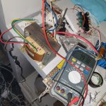
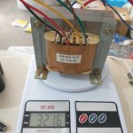
Are you able to measure the primary and secondary resistances?
That will give a clue (but needs a bit of thinking about) to estimate the ripple and performance.
You could also try a bridge rectifier and a smoothing capacitor across one secondary, measure the open load voltage (we would expect around 11V) and then place a 10 ohm resistor (would have to be rated at 10W or more and put on a heatsink, if you have them) and measure the D.C. voltage.
Depending on how well designed the transformer is you may or may not find running the 220V winding works. You did not say what voltage you have available, but I guess it is 230V. Running the 220V should not be a problem but if the designer did not allow enough margin the magnetic field may saturate the iron and it will get hotter than it ought. It isn't the 230V that is the problem, it is the tolerance to a higher than normal voltage which may be getting on for 250V. Do you know what your supplier's min/max voltage ratings are?
Fast diodes won't help much for low frequency supplies. Schottkys may be better for your low voltage application as long as they can handle the current. What is important is the average current rating and maximum peak which you should get datasheets for. Some Schottkys might conduct at a lower voltage than silicon at lower currents but not be a lot better at high.
For your lower power unit I suggest that you actually need a circuit which would be something between the '69 and '95 variants. For maximum output at lower voltage, you should use a bootstrap rather than a CCS (or at greater expense, build a voltage boost converter to drive the CCS from a higher voltage). You could use the input stage of the dual rail supply for the front end.
And JLH's original construction was on Veroboard or similar. You could use that approach too.
Last edited:
- Home
- Amplifiers
- Solid State
- JLH 10 Watt class A amplifier