I already used jfet in CCS, I put a link to the old circuit in my post before.In general a JFET current source is much quieter than one using depletion mode MOSFETs.
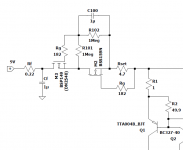
Unless you need more voltage than 50V, I personally would use a 2SK208GR or 2SK209GR cascoded by a 2SK209BL to make up a 3mA CCS.
Fine adjustment with a single source resistor for the (lower) GR-grade JFET.
And just use multiple in parallel if I need more current.
View attachment 1059404
Patrick
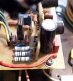
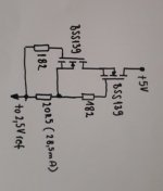
However the last month I have experimented a lot with BSS139 and BSS159, with them I have replaced all the jfet I had in CCS's. Surprisingly, it works better than any jfet I've tried that is available today. The BSS139 even works in a cascade at just 2.5V voltage drop. Currents are a bit higher, around 25-30mA. Even as an anode CCS (14mA current) the combination of IXTP08N100D2 and BSS159 with bias multiplier works better than IXTP08N100D2 with double jfet.
Attachments


@ Petr: I don't know why no one comments on your well-documented work, I don't have the skills, but two questions come to me, can we still call this diagram "JLH", and ESPECIALLY, the did you make it work in real life and compared to the original?
Huggygood, today amp design starts with modeling. When using correctly executed transistor models, the parameters of virtual amplifiers are quite close to the parameters of real amplifiers. I know that the JLH-69 amplifier is still very popular all over the world. Therefore, I was interested in the version of the inverting amplifier proposed by Dreew. What this modification gives, I tried to reflect as much as possible in the tests.
What does this version provide?
I really hope that someone from the forum visitors will make a layout of this version in hardware and share their experience of setting up and listening to it.
What does this version provide?
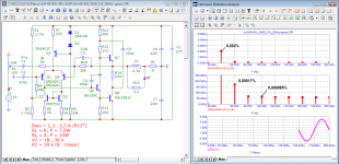
- 30 dB more loop gain (30x);
- introduced non-linear distortions are significantly reduced;
- there are no switching distortions;
- high-speed distortions are small, do not exceed the level of non-linear distortions;
- wider bandwidth of full power;
- the power supply is simplified - there is no need for an electronic filter that slows down the rise in supply voltage and the charge rate of the output capacitor.
I really hope that someone from the forum visitors will make a layout of this version in hardware and share their experience of setting up and listening to it.
Attachments
Regarding resistance to reactive loads, Ben Duncan writes the following:
«Some power amplifiers, often those with reduced or nil global NFB manage with a rudimentary OPN, often comprising just the Zobel. These are so called ‘output inductorless types’. They first appeared in the early 1980s after some of the UK’s high-end, low budget domestic power amplifier makers identified a consistent and valuable improvement in sonic quality when the output inductor was excised. As the inductor was almost certainly not of the special calibre that is required, this is hardly surprising. The motto ‘no component unless essential’ is admirable, but inductorless power amplifiers are renowned for becoming RF unstable and even blowing-up, when low inductance speaker cables are connected. This problem is definitely in the amplifier supplier’s court, unless the maker states specific cables that must or must not be used.»
Note. The linear inductance of a conductor with a diameter of 1 mm is 1.5 μH. To ensure the stability of the amplifier, 0.1 ... 0.2 μH is often sufficient
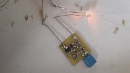
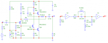
Inductance L1 0.2 μH consists of 4 turns of wire with a diameter of 1 mm, wound round to round on a 9 mm mandrel.
«Some power amplifiers, often those with reduced or nil global NFB manage with a rudimentary OPN, often comprising just the Zobel. These are so called ‘output inductorless types’. They first appeared in the early 1980s after some of the UK’s high-end, low budget domestic power amplifier makers identified a consistent and valuable improvement in sonic quality when the output inductor was excised. As the inductor was almost certainly not of the special calibre that is required, this is hardly surprising. The motto ‘no component unless essential’ is admirable, but inductorless power amplifiers are renowned for becoming RF unstable and even blowing-up, when low inductance speaker cables are connected. This problem is definitely in the amplifier supplier’s court, unless the maker states specific cables that must or must not be used.»
Note. The linear inductance of a conductor with a diameter of 1 mm is 1.5 μH. To ensure the stability of the amplifier, 0.1 ... 0.2 μH is often sufficient
Inductance L1 0.2 μH consists of 4 turns of wire with a diameter of 1 mm, wound round to round on a 9 mm mandrel.
Hi huggygood,@ Petr: I don't know why no one comments on your well-documented work, I don't have the skills, but two questions come to me, can we still call this diagram "JLH", and ESPECIALLY, the did you make it work in real life and compared to the original?
I think the answers to your questions are ‘No’ and ’No’
... Perhaps, the answer should be YES, YES.
In the past we have seen many parametric changes to the original design including many substitutions of different transistors. Also there were several more radical, structural changes. For example I have more recent 22W version, rather different from the initial design. Petr proposes an interesting radical change of the original design. I am eager to see what impact can this iteration bring in practical, real-world lay-out. From the published data this change may reduce distortion while maintaining the original sound character. I'm curious to see more.
In the past we have seen many parametric changes to the original design including many substitutions of different transistors. Also there were several more radical, structural changes. For example I have more recent 22W version, rather different from the initial design. Petr proposes an interesting radical change of the original design. I am eager to see what impact can this iteration bring in practical, real-world lay-out. From the published data this change may reduce distortion while maintaining the original sound character. I'm curious to see more.
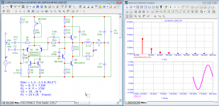
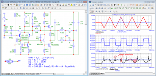
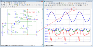
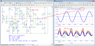
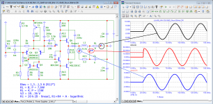
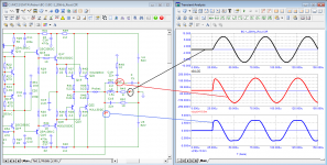
Here is the operation of the two versions when the load resistance changes. In the original scheme, depending on the load, a constant component appears in the distortion products.
Attachments
......which has significant implications to the design and sound that it produces so, in which case, and with all due respect, it is not the original JLH amplifier. Yes there are many variants 'based' on the 1969 amp, but they are not the 4 transistor simple design. The answer to the first question is 'No'.... Perhaps, the answer should be YES, YES.
Petr proposes an interesting radical change of the original design.
Further, where is the practical implementation and not just a modelling - the answer at the moment is 'No' and cannot be 'Yes' - see the answer to question 1.
I must add that the original JLH measures badly but sounds wonderfully good as long as it is connected to a single speaker (1 speaker or two).
he is not comfortable on rhythmic music or rock but is perfect on jazz or classical.
let's say it's not an amp that does everything well, but what it does it does wonderfully well, I often compare it to the Elipson 1303 to which it is very close in many ways.
he is not comfortable on rhythmic music or rock but is perfect on jazz or classical.
let's say it's not an amp that does everything well, but what it does it does wonderfully well, I often compare it to the Elipson 1303 to which it is very close in many ways.
Indeed, but, it is premature to disqualify this variant without a practical rationale. This will be my Summer 22 Project. I already have almost all components. Let's wait for Autumn 22. 🙂......which has significant implications to the design and sound that it produces
Human taste is a mistery: good tap water tastes better than any kind of purified water. Just try to drink rainwater or distilled water and you'll feel the difference, without chemical analysis. Our perception is better in that area.original JLH measures badly but sounds wonderfully good
Many amplifier designers attach great importance to the damping factor, which is responsible for the output impedance.
For example, Mati Otala was a supporter of the high frequency of the first pole, in which the output impedance in the entire sound range is constant.
Let's check the output impedance of the original JLH-69 circuit and the modified version.
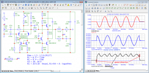
When a voltage equal to RL (8 Volts) is applied, the output impedance is approximately equal to the voltage drop at the amplifier output in Volts.
In this case, the output impedance of the JLH-69 is 0.175 ohms and is in phase with the external voltage.
The output impedance of the modified version is 0.025 ohms. In this case, the output voltage to the inductance L1 is only 3.75 mV, or the output resistance at this point is 0.004 Ohm and it is in phase with the external voltage.
For comparison, let's check the output impedance of the BC-1 amplifier. The output impedance is 0.2 ohms and is out of phase by 90 degrees. The output voltage to the inductor L1 is 0.003 mV which means that the output impedance at this point is 0.003 Ohm, but it is highly distorted and also shifted by 90 degrees.
For example, Mati Otala was a supporter of the high frequency of the first pole, in which the output impedance in the entire sound range is constant.
Let's check the output impedance of the original JLH-69 circuit and the modified version.
When a voltage equal to RL (8 Volts) is applied, the output impedance is approximately equal to the voltage drop at the amplifier output in Volts.
In this case, the output impedance of the JLH-69 is 0.175 ohms and is in phase with the external voltage.
The output impedance of the modified version is 0.025 ohms. In this case, the output voltage to the inductance L1 is only 3.75 mV, or the output resistance at this point is 0.004 Ohm and it is in phase with the external voltage.
For comparison, let's check the output impedance of the BC-1 amplifier. The output impedance is 0.2 ohms and is out of phase by 90 degrees. The output voltage to the inductor L1 is 0.003 mV which means that the output impedance at this point is 0.003 Ohm, but it is highly distorted and also shifted by 90 degrees.
Attachments

More of the same "improvements" that dozens of other have proposed, only to be disappointed by the result. (I have one in the shed. The JLH remains in service)What does this version provide?
- 30 dB more loop gain (30x);
- introduced non-linear distortions are significantly reduced;
- .
As discussed earlier in this thread, high loop gain and a differential input stage are unlikely to result in a good sounding amp.
Mostly because this amplifier will be clipped. There's probably a few other factors
More of the same "improvements" that dozens of other have proposed, only to be disappointed by the result. (I have one in the shed. The JLH remains in service)
As discussed earlier in this thread, high loop gain and a differential input stage are unlikely to result in a good sounding amp.
Mostly because this amplifier will be clipped. There's probably a few other factors
Let's not guess on coffee grounds. Give a diagram of what you have in the shed.
Diagrams play no music.
Real amps do play.
if you look only at the graphs of THD and count the number of zeros after the decimal point, then I agree that there really is no correlation with these graphs and the sound quality. That's why I ask you to show the diagram of the amplifier that was rejected and now stands in the barn
It wasn't me 😉
The important point here is that you should open new thread as your creation have nothing to do with JLH 10.
It will only confuse people looking for legendary little gigant.
JLH 10 survived decades of "improvements" only to shine like never before. Todays builds proove that JLH 10 have qoulity over those thousands if no milions others collecting dust in the shalves.
I would never dare to change anything in the JLH 10 circuit and pronounce it like improvements. It will take lot of experience, work and even luck to come close to JLH, not to say "improve" something.
Not saying there are no better things, just that it is not like simply only throw differential pair and cascode or current sources in, give few watts more and measure the success.
That's the point.
- Home
- Amplifiers
- Solid State
- JLH 10 Watt class A amplifier