I think it's too late to add safety warnings when you've already piqued the interest of curious folk looking to save expenses, space, weight etc. - probably the kind who are most at risk by understanding least about mains and switched mode supply safety 😉.
Something like this is usually adequate to keep switching noise out of the local mains supply: 5120.2000.0 | Schurter,1A,250 V ac Male Snap-In IEC Filter 5120.2000.0 None Fuse | RS Components
It occurs to me that SMPS manufacturers go to a lot of trouble to isolate the output voltages from the input and usually employ optical isolators for the regulation feedback. It may be disastrous if that were ignored by effectively shorting input and output grounds either at the power supply or through the grounding of the rest of the audio system 😱.
Mains filters of the type mentioned usually don't work very well, about as well as paracetamol against the flu. They are seldom better than the 470 nF. Most often they have four capacitors and a common mode choke of circa 1 mH. Seeing that the Meanwell has a fairly large common mode choke I suspect that is already taken care of. The typical off the shelf filter often has 2 x 4.7nF class Y2 capacitors. These come.into effect at about 1 MHz to offer some additional common mode or ground to live filtering. Although ground to neutral shouldn't need filtering that ignores inductance that causes a noise path.
The big deal of this experiment was to show that what is often thought to be true isn't. By considerably increasing the capacitance at the input almost nothing happened. What did happen was the noise was slightly nicer where not hum related. As to safety, it's probably no more dangerous than anything involving mains electricity. Amazingly we need an electrician to do a simple addition to an electrical circuit in the brick work or building structure. However sockets and light fittings are DIY projects under regulations. Often a socket where ring and spur is a tough job.
What I will attempt is better output filtering.
On safety. I wanted some liquid nitrogen in quantity. When asking what safety precautions the supplier said same as boiling water. He then laughed and said boiling water is very dangerous. Nothing stores heat better than water. Danger is about alerting people to danger. For example wine is dangerous. People never say it that way. Let's be clear. Where 330 VDC is involved 99% should leave well alone. On that point I think I had a dip in voltage during my tests. The figures given implies less going in than coming out. The actual consumption of everything was about 64 VA The output 48 watts as it was pure resistance. That'll suggests about 90% efficiency.
I can create a generic copy of an offer the shelf filter to measure. If it's vaccine or paracetamol we will know. Theoretically the problems the off the shelf filters solve is RFI. Tasima a low cost filter is tuned to 70 kHz I am told. That is if you like paracetamol plus. I was impressed when told that. A lady designed it. A friend. Ex BBC engineer.
By the way. I find the Meanwell smps if connected ground to 0 volts it blinks and swiches off. Reading up this is typical. Apparently the optimum internal ground to 0 volts capacitance gets the best RFI performance. I tried to increase that capacitance without any luck.
Valve amplifiers using el34 typically work at 450 VDC. Even though using an isolation transformer they use a common to ground 0 volts connection. That's very dangerous and the isolation transformer offers no protection due to common ground. That's more dangerous and typical. It's far more dangerous to imply safety that isn't there.
Valve amplifiers using el34 typically work at 450 VDC. Even though using an isolation transformer they use a common to ground 0 volts connection. That's very dangerous and the isolation transformer offers no protection due to common ground. That's more dangerous and typical. It's far more dangerous to imply safety that isn't there.

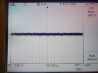
This is the best result and reasonably safe. If a person can not wire a 470nF capacitor ( class X2 ) they can not wire the SMPS. The only thing I couldn't try was a big choke to the output. Electronic ways would drop too many volts. Notice how good a LM317 is. It can be much worse if the notes on low noise are ignored. 10 000uF at the output sent the SMPS into protection. I dare say a low drop out voltage regulator could do the job. Watch out for oscillation if doing that.
I feel the DC input to the SMPS a waste of money.
A garage owner who got angry with the government inspector had his garage closed because bleach wasn't in a locked cupboard with poison warning. Thinking about it it's unusual we can by bleach.

I solved the problem of the filter. The 24V relay needs to be a high current type preferably higher resistance coil ( > 1000 ohms ). The reversed diode is the usual precaution not really required here. Might save the capacitor if SMPS connected the wrong way around. How the circuit works is relays usually come on at 2/3 voltage. This just about makes the load possible as the instananeous current whilst very high isn't imposssible. The 22R was the tweak it required to work. The PSU had to think about it once or twice. Most relays are OK at 120% stated voltage. The relay must be open contacts when off. The contacts short the 10R+22R ( 6R8 ). The Meanwell RS 50 just about gave 2 amps. The filter is about 15 Hz - 3dB. It should be 15 db down at 75Hz and better than 20 db at 150 Hz. Like anything like this sucess is by experiment. You could use a timer chip if prefered. No real need as the circuit provides a delay.
This must be very close to the sound of a linear supply. Being class A helps. As said the 100 watt version best choice. I like the PSU as it offers 20 VDC if mildly overloaded. That's quite handy. Back it off to get 28 VDC.
I did a similar 'soft start' on a linear supply with BIG caps: using the capacitor voltage to trigger a relay that shorted a series resistor on the primary of the transformer, but I used Zeners to adjust the voltage when the relay was triggered. Worked very well, simple is beautiful 🙂
JLH liked simple ideas. He was very surprised when friends said publish his hobby design. Apparently in later life he was treated as a guru and this astonished him. He to me was s genius. Often people mistake simplicity with not being very good. 0.01% Thd from a tweaked version using four packages. That's amazing. I have bought the cheapest MJ3001 and 2N3055 to see if I can build that one. BC327/337-40. Doubtless some frequency compensation required as the bottom part is a Darlington triple.
Last edited:
BTW the delay circuit seems to allow a grounded oscilloscope to be used which was impossible before . As others have said it seems to make noise greater. There was some MHz output at about 5 mV that wasn't seen before.
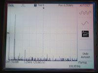
Note the IM products are all over the place, in vast numbers. This is the true nature of non-linear distortion.
Note that IMD is program related. That is, IMD products on a solo monotone instrument (voice, sax, cello) are going to be vastly different to that from massed choir and organ or an ensemble playing "difficult" music.
That is, the same reproduction chain will sound different depending on the music you choose.
Further, different music will find different limits (i.e. clipping) in systems.
So, while my JLH + Lynn Olson's Ariels are bloody wonderful (including being loud enough) for most of the listening I do, some material (e.g. Depeche Mode "Personal Jesus") points out the limitations of this set up rather rapidly.
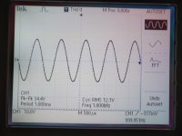
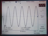
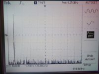
Today I was doing some measurements on my JLH69 amplifier. Power is classic, toroid + CRCRC filter + voltage regulator, +/- 19V 8A.
All transistors are fast, minimum ft 60MHz on 2A for output transistor. The current through the output transistors is 2A.
https://www.diyaudio.com/forums/solid-state/3075-jlh-10-watt-class-amplifier-554.html#post5759789
All transistors are fast, minimum ft 60MHz on 2A for output transistor. The current through the output transistors is 2A.
https://www.diyaudio.com/forums/solid-state/3075-jlh-10-watt-class-amplifier-554.html#post5759789
Attachments
-
 jlh69 +-19V power supply.jpg225 KB · Views: 481
 -
 jlh69 18W 8ohm.jpg230 KB · Views: 476
 -
 jlh69 fft 18w 8ohm.jpg224.5 KB · Views: 461
 -
 jlh69 12W 8ohm.jpg269.2 KB · Views: 374
 -
 jlh69 fft 12w 8ohm.jpg259.9 KB · Views: 367
 -
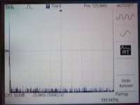 jlh69 fft 12w 8ohm 2.jpg226.1 KB · Views: 140
 -
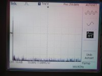 jlh69 fft 14w 8ohm.jpg234.8 KB · Views: 137
 -
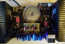 JLH69 grunf.jpg356.4 KB · Views: 268
Today I was doing some measurements on my JLH69 amplifier. Power is classic, toroid + CRCRC filter + voltage regulator, +/- 19V 8A.
All transistors are fast, minimum ft 60MHz on 2A for output transistor. The current through the output transistors is 2A.....
That's a very nice looking assembly 🙂 What is your actual power supply since a 19V supply would only require 2A bias if the speakers were say, 3 Ohm or less. A +/-19V supply implies a total rail-rail 38V which would stretch the recommended limits of the '69, original design. It likely would suit the JLH'96 and later versions with dual rails and 8 Ohm loads.
Last edited:
JLH had doubts about very fast output transistors and was at a loss to say why. As far as I know he never found out. Next generation faster transistors were liked. BDY56 being an example. My feeling is speed is irrelevant. What might be ultra important is a quality called super beta by Douglas Self. Self also says better to add high grade capacitors to a device than see the transistor capacitance as a virtue. Self also plays down IM distortion saying excellent THD and poor IM seems unlikely. It should show up somewhere. Much as Self and myself wouldn't agree about the Blameless concept I do like the bench marks he set. Rod Elliot of esp audio had an interesting point to make. He said he didn't feel simple amplifiers of the JLH type were more stable due to simplicity, instead it is high capacitance transistors especially for the VAS. I have doubts that applies to the best. However he probably has a point. My JLH required 33 of VAS compensation. Here is a thought. The average value of a sine wave is zero. How come we can hear a sine wave? That is because it is a power wave. As current is proportional to current we can use sin^2 to express that as V^2. Now magically there is no negative value of 180 to 360 ddgrees. It also explains RMS. Sin 45 is 0.7071 which is the accepted DC equivalent level. That's bonkers as simple calculus of how the curve looks. Sin^2 45 is 0.5 , that makes sense. A Pythagorean solution of a 1 x 1 x 1.414 triangle. What does sine squared look like? A distorted sinewave. If we add phase shift into the story we realize how distortion testing probably doesn't tell us the whole story. Sine 0,30,45,60, 90 , 0, 0.5 0.701, 0..866, 1 Sin^2 0, 0.25, 0.5 , 0.75, 1. Notice how the number is the actual clock face number and better describes the process. The other thing to remember is our use of sine waves is related to the invention of television.
2/π is another accepted average value related to rectification. It is about 1.11 times smaller. The fiure is called form factor. In 1974one afternoon in the last five minutes or the lesson we were taught that. The master said he wasn't sure why we were doing it as it was dying out as a concept. When 15 at school Mrs Grundy our physics teacher taught me RMS. She had been a senior radar engineer. It's only recently I had to understand it better than she taught. It was like a science fiction film as she derived and simplified the maths. She was not always easy to like. I liked her.
2/π is another accepted average value related to rectification. It is about 1.11 times smaller. The fiure is called form factor. In 1974one afternoon in the last five minutes or the lesson we were taught that. The master said he wasn't sure why we were doing it as it was dying out as a concept. When 15 at school Mrs Grundy our physics teacher taught me RMS. She had been a senior radar engineer. It's only recently I had to understand it better than she taught. It was like a science fiction film as she derived and simplified the maths. She was not always easy to like. I liked her.
I don't know what Self means by "super beta", that was a term used a while back for transistors with a very high gain (over 1000). In the JLH amplifier, modern output transistors with "flat beta" I would suggest is a better if more mundane description, having a gain more or less constant with current over a wide current range, and in particular, maintaining the gain at high currents, is particularly relevant for lower distortion. Unlike the 2N3055 which had a peak gain of perhaps 200 at 200mA but only 30 at 4A.
Regarding IMD, that is primarily why low THD is required. Since low THD implies linearity, IMD should be low. Amplifiers with THD around 0.1% could have quite high levels of IMD, which as people are pointing out depended on the degree of complexity of the music signals.
Transistors like the BDY56 were intermediate: higher ft, yes, but not "flat beta". For output devices, they should have been an improvement over the 2N3055. But for stability, a lower frequency VAS device would have been required, or compensation capacitors needed.
Some time ago I made a "shrinked" down-rated version with D44H11 ouputs. Worked ok, needed extra compensation and had more "in-your-face" sound which wasn't bad.
I bet the sound is quite ... "warm", heh heh....
The current through the output transistors is 2A.
...
Today I installed voltage regulators in my JLH69 . It is a Walt Jung superreg that I boosted a little. The output voltage is +/-20V and can withstand currents greater than 4A.The voltage drop for good regulation is 4V.
The difference in sound was immediately felt. It was as if I was removing the curtain from the speakers, so many new details came in, the quality of the recording and the studio was exactly felt, the sound stage was literally in my living room, it really sounds wonderful.It played great before, but now it has gone to a higher level.
A few days ago I inserted another RC element into the power supply, so I had 30000+30000+30000uF old + 24000uF new, the resistors between were 3x0,24R, there was a difference on the oscilloscope and also in the sound but not like today with the regulators. At the moment I put jumpers on the resistors so I do not have a voltage drop of 2.5V on them. So I provided a larger voltage drop for the regulators. For the test I will reset it, but then I will have to adjust the regulators to a lower output voltage.
My plan is to make another pair of regulators so that I can separate the power for both channels. I think that will be the final step for this amplifier and I think then I might experience sound enlightenment.🙂
https://refsnregs.waltjung.org/Improved_PN_Regs.pdf
Is the pcb for this regulator available for sharing?
Hi John. I possibly mix up the terms. Douglas says the gain is high ( not Darlington ) and is excellent into low resistance loads, sustained beta is the term used as his own idea. When driving very low loads 2N3055 has a gain of about 5. On the other hand it will permit very high base currents. Gogny a French design had a 3055 driving a 3055. This reliably gave 50 watts one ohm for the Gogny ribbon speaker ( With feedback into the amp from the ribbon, my French thought this said it was to damp resonance, I could be wrong, 1967 ). That's the problem, The 3055 and most driven by a puny driver stage is going to suffer. If class AB it wouldn't work at all. Very often high Ft transistors have the ideal gain. I will try the MJ3001 I bought. JLH wasn't sure if he liked it. The standard measurements at the time were excellent with is. THD 0.01%. I will have to build the Elektor 28V 40 mA lamp state variable filter oscilator to measure that. TL074 - 108 dB at 1kHz. The problem is outside of 1kHz it's less good. All the same for a JLH its fine. Hope this link works. Buy the book if you don't have it.
Audio Power Amplifier Design Handbook - Douglas Self - Google Books
I must take distortion as a current waveform into a real speaker. I have a tough speaker I can use. My speaker cable is a higher resistance type. That could be enough. Picoscope show how to do a composite measurement. I have a hunch the cheaper 2204 can do this? There Colleen Christmas sorted, a Picoscope. Hers is a chainsaw( ! ), a pair of boots, and some Beatles LPs she hasn't got. CPC seem to have a good price on Picoscope. 10 MHz or 25 MHz if the 2205. 10 MHz is often enough. My old scope is getting to the end of the road as it needs Windows XP to work ( or before ). I am rebuilding a PC just for it ( Colleens old one which only was kept due to photos on it's hard drive ). The Picoscope even runs Linux which I have. I haven't found anything better for £100. The problem is anything truely better is vastly more. That is unless others know better.
One idea I would like to try is lead acid battery with 1 uF shunt cap against all volage regulators. It would be interesting. 24 VDC or 36. Anybody tried it? Lithium types. Any cheap option from tools or whatever.
My conversion to SMPS was Hypex. I had to work hard to better the Hypex SMPS. It was bright, far from harsh. It measured worse than I thought. Plenty of noise. I think the Meanwell better. Doubtless the Hypex was doing that to the SMPS, 60/400 kHz beat. I might go to 2u2 input cap on the Meanwell. It semeed not to go mad when I did.
I left the Hypex on the bench for hours at 1W rms only it wasn't. It was near 90. The 10:1 probe. It was on a piece of 2 mm metal of a Naim Nait case. It was hardly warm. The probes were scrap afterwards. If you are looking for a cheap 8 ohms load a Bosch 1600 watt half moon cooker element is usuable as it has a halfway tap. 32 and 16 ohms also. The cheap generic ones are fine. Lowish inductance. 1/4 inch terminals.
I built one of these amps back in the early seventies but it ran too warm with the heat sinks I had available to me at the time (they were 'free'). But what I can't understand is why you would need to (in modern times) actively regulate the PSU given the constant current drain?
I built one of these amps back in the early seventies but it ran too warm with the heat sinks I had available to me at the time (they were 'free'). But what I can't understand is why you would need to (in modern times) actively regulate the PSU given the constant current drain?
Alas the current drawn from the power supply by this "JLH" amplifier, is not constant when playing music and driving an 8 ohm load.
Some people prefer voltage regulated supplies because this completely eliminates (2 x fmains) ripple voltage on the rail(s). If the amp has less than excellent PSRR, giving it a stout and constant, regulated power supply is a proven fixup.
- Home
- Amplifiers
- Solid State
- JLH 10 Watt class A amplifier