Interesting, thanks, but doesn't it also increase the back impedance of the PSU by having active devices in the chain, or have things moved on?
Regulated PSU output impedance is less than 1 milliohm when delivering 1 ampere of load current through a BJT series pass transistor, using a regulation error amplifier like NE5532 whose gain*bandwidth product exceeds 8 MHz.
To get the same output impedance at 150 Hertz in an unregulated supply, you'd need a total of 1.1 Farads of capacitance -- with zero ESR.
To get the same output impedance at 150 Hertz in an unregulated supply, you'd need a total of 1.1 Farads of capacitance -- with zero ESR.
I remember somebody (Bigun ?) reported improved PSRR using a RC on the supply to the low power part of the amplifier (all except outputs). I would be interested in trying this, but since I have various versions, I'm a bit confused on how to do it on each version.
-NPN -69 with floating ground
-PNP -69 (zerozone) with floating ground
-Dual output&dual supply with 2xCCS (ESL?)
(+ more on the way..)
I guess the floating ground could be considered dual supply too.
In these cases, is there a benefit to put another RC on the negative rail too?
I guess the options are one RC on positive, with cap going to -, or 2xRC on + and - with caps going to GND?
Hoping somebody could simulate it, or maybe know the answer already?
Member
Joined 2009
Paid Member
I remember somebody (Bigun ?) reported improved PSRR using a RC on the supply to the low power part of the amplifier (all except outputs).
I simulated a capacitance multiplier on the rail to the front end of the amp, this was the best option for psrr without having any restrictions on the rails to the power stage. In the end I found an RC was perfectly good enough. You can see it here: TGM9 - my version of the JLH '69 Class A amplifier
Thank you! I know I saw it somewhere while going through this thread before..(too much information to digest)
If I'm reading it correctly, all that is needed is RC from positive rail to GND? No advantage on putting another one negative rail to GND?
If I'm reading it correctly, all that is needed is RC from positive rail to GND? No advantage on putting another one negative rail to GND?
Member
Joined 2009
Paid Member
I made only a single rail version, more in the spirit of the original. Sometimes there is not much benefit from putting it in the -Ve rail of a dual-rail amplifier - I remember Hugh Dean telling me he found insufficient benefit in his earlier AKSA related amplifiers. I'd suggest you try simulating it. Remember, with dual rail version, the feedback cap needs to return to signal ground NOT the -Ve rail as was shown by error on some schematics.
My simulation skills need improving (a lot).. But on the other hand, this is the perfect learning amp, few components and sounds good.
I'm using single supply and floating ground with capacitors (as sublimed JLH), and no capacitor on the feedback resistor to GND. Not sure how that capacitor would affect the subsonic woofer swing at power up..
I'm using single supply and floating ground with capacitors (as sublimed JLH), and no capacitor on the feedback resistor to GND. Not sure how that capacitor would affect the subsonic woofer swing at power up..
I am still using the 1996 version in which the output standing current is 2A. The dual rail supply has 30,000uF of capacitance in each followed by a regulator for each.
There was a lot of heat dissipation in the regulators and some excess voltage from the supply so I took the opportunity to reduce this by including a pair of chokes between the rectifier and the supply capacitors which had the effect of reducing ripple presented to the regulator.
Small changes like this and getting the earthing sorted make a lot of difference to the sound. Mark Johnson is right on regulated supplies I rate the 1996 design as better than the 1969 version I built 20 years earlier with the capacitance multiplier supply smoothing. This was my first DIY build.
I remember visiting a Hi-Fi shop when Naim amplifiers first arrived in this country and being impressed by the NAP 250 model which uses supply regulation.
There was a world of difference in the bass transient performance between this and my 1969 JLH which is due to the Naim having a lower power supply impedance.
The1996 JLH uses 3 terminal regulators in combination with a power transistor bypass. The original circuit called for 7815/7915 types - I substituted 317/337 types which I am happy with.
The bandwidth of an audio grade IC as Mark has suggested I think would do a better job with a supply using less capacitance.
I have had thoughts of replacing the 317/337 with a pair of chip amplifiers like LM1875 but I am satisfied with things the way they are.
For a single supply amplifier like the JLH 1969 for a low parts count /cost approach one could try using a 5A rated regulator such as LM338
Last edited:
Member
Joined 2009
Paid Member
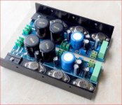
building on the nostalgia approach, a 2N3055 based regulator with the '69 using 2N3055 outputs would be nice.
Here's one I prepared earlier:
Based on Rod Elliot's Cap Multiplier circuit, it gives (in theory) an effective capacitance of about 6.6 Farads. (470uF x gain of the Darlington) Simulation shows about 250mV of sawtooth input dissappearing on the output.
Cheers
Mike
Based on Rod Elliot's Cap Multiplier circuit, it gives (in theory) an effective capacitance of about 6.6 Farads. (470uF x gain of the Darlington) Simulation shows about 250mV of sawtooth input dissappearing on the output.
Cheers
Mike
Attachments
There is a strong element of caveat emptor about this sort of multiplier circuit in that there is no short protection so if something goes wrong you could be looking at replacing the power transistors and the drivers in this part of the circuit.
These will blow before the fuses do even if these are changed to fast blow types. With the 1996 dc coupled version this could put dc on the amplifier output which will take out bass speaker voice coils - a relay delay dc speaker protection is a must for this amplifier.
These will blow before the fuses do even if these are changed to fast blow types. With the 1996 dc coupled version this could put dc on the amplifier output which will take out bass speaker voice coils - a relay delay dc speaker protection is a must for this amplifier.
There have been a string of Ebay JLH'69 kits, PCBs and fully built amplifiers that might fit this description.building on the nostalgia approach, a 2N3055 based regulator with the '69 using 2N3055 outputs would be nice.
'not saying they are particulary good products and the rectifier location worries me. Also, some versions may only be simple cap. multipliers that would need modification but they look attractive, simple and compact assemblies - a good way to get started with a better power supply if you have a suitable transformer, capacitors and heatsinks to meet the higher voltage and dissipation needs.
I bought just the PCBs for around US $10 including post. In the meantime, a friend had bought a fully assembled amplifier which used similar PCBs. I was somewhat impressed and no longer curious so for now, that project is relegated to the ever-growing list.
Attachments
I simulated a capacitance multiplier on the rail to the front end of the amp, this was the best option for psrr without having any restrictions on the rails to the power stage. In the end I found an RC was perfectly good enough. You can see it here: TGM9 - my version of the JLH '69 Class A amplifier
I have tried some simulations (very time consuming business), and nothing I do improves the PSRR with single supply, and floating ground. I induced 66kHz 0,5V sine to simulate my switched PSU (laptop brick), guesstimating a supply impedance of 0,1ohm.
The best I could get was 'as is', and then the ripple on the load was abt 4mVpp. As soon as I started adding some RC to GND or between rails etc, the ripple got worse. It seems no extra caps at all is best. Even connecting the smoothing cap for the offset bias resistors for the input transistor made it slightly worse.
The ripple in the midpoint between the main caps (- to load and virtual ground) is far greater then the ripple on the load, so it seems the amp is cancelling some of this midpoint ripple, and as soon as I do some filtering, there is less cancellation.
Maybe there would be some way to tune the cancellation to improve it, but I have not figured out how. Maybe even the 'offset trimming' might affect the ripple on the output.
When I did an FFT plot in LTspice, some small 'mirrors' of the 66kHz can be seen on the plot all the way down to 1kHz, but they are really low. I have not seen this in distortion measurements (FFT), so I'm pretty confident they are under -100dB.
From memory, the measured ripple with the switched supply was abt 2mVpp to the load in reality, but I think the ripple from the PSU is also less than simulated.
One problem with the floating supply, is the turn on subsonic 'thump'. I figured this comes from charging the input cap, since it needs abt 0,7V over it before the balance is reached. Have not found any solution for this either..
That's it for now 🙂
Last edited:
I am away from my test equipment so can't do accurate tests.1R 10 000 iuF seems to suppress nearly all the smps noise. 20dB improvement at 66 kHz. In theory it should be better.I don't really mind as the noise has reached the noise floor. A LM317 is miles better. LD1084/5 if wanting more current. They seem as good and low dropout My research into real world power supplies suggess LM317 gets close to being as good as you can want. It is remarkably easy to get working. TNT audio tell about it's competitors. I did build a TL431 with power transistor. Very good and very fussy. Shunt regulators are projects in themselves. Tl431 is a low current shunt device not unlike a perfect zener diode. Some versions have much lower noise. Take the capacitance graphs seriously.
Hi Nigel. On regulation with TL431, can you point us to your preferred design and clarify the fussy aspect?
I have only 19,5V from my laptop bricks, so I try to avoid any voltage drop from resistors or regulators.
@Rallyfinnen, you can buy these or variable 9-24V versions very cheaply if you are limited to Laptop bricks: ac 100v-240v dc 24v 4a 96w power supply charger converter adapter Sale - Banggood.com
Hi Nigel. On regulation with TL431, can you point us to your preferred design and clarify the fussy aspect?
I don't have exact examples as I had doubts about if it really was better than LM 317. The design was from the manufacturers data sheet. The problem is converting the paper pdf example into a working circuit. That often produced loss of ripple rejection. The other problem is the TL431 can move easily go unstable compared with the LM317/ LD1084. This comes down to choice and placement of capacitors. Definitely this needs test gear.
I did try adding a LM317 onto a smps It didn't work well. I talk about LM 317 because many people assume because as it is cheap it can't be any good. It is to me the one to beat. The LD1084 even more so.
LM 317 is a slightly better LM7812. It is if you like a LM 781.25. The 1.25 V is multiplied to whatever you want by using two resistors. One usually is 240R the other is like the calculation for a non inverting amplifier V = 1 + ( Ra/Rb ) Rb being 240R. The other resistor can be bypassed by a 10uF capacitor to significantly reduce noise. 20dB for 15 pence. 47 uF shows a small improvement and no obvious downside. LD1084 should be less stable. I didn't find that. Many lower loss types are.
Now we come to the reason for all these words. People say this or that voltage regulator had a good or bad sound. If bad very likely they didn't measure it. If you think about it the series regulator is a single ended amplifier bouncing on top of the actual amplifier. 1 MHz bounce rate if very lucky. Realistically much slower. The typical output capacitor helps overcome that although not the stated reason it's there.
It's all very well thinking regulators sound different. Like cooking the ingredients and a cookbook don't guarantee a Mitchelen star. LM317 like making an omelette. Great results considering how simple.
@Rallyfinnen, you can buy these or variable 9-24V versions very cheaply if you are limited to Laptop bricks: ac 100v-240v dc 24v 4a 96w power supply charger converter adapter Sale - Banggood.com
I'm not really limited to using bricks, but they seem to offer good performance for the money (especially since I got them for free from old laptops at work). I actually have a similar adjustable, but the ripple from that one is really bad compared to the OEM bricks I use, and it does not start if I have big caps connected.
I tried to simulate a std 69 version with the same 66kHz supply ripple, and for some reason there is more noise to the load with RC to the low current part of the amp, than without. However, with 100Hz ripple, there is a major improvement with RC.. seems strange to me.. I use 5-10ohm and 4700u RC.
- Home
- Amplifiers
- Solid State
- JLH 10 Watt class A amplifier