Member
Joined 2009
Paid Member
One needs to be very careful when making such statements, as the clueless (and biased) run away with them make inferences that are not valid.
Specifically, the inference that the behaviour of a triode (as a three port device) and the behaviour of a classic differential-amplifier-plus-gain-and-pole feedback circuit (e.g. an opamp) have anything in common beyond the output conditions affecting overall circuit behaviour verges on the disingenuous.
I view them as quite equivalent and the issue not one of disingenuous but of lack of understanding. The key for any feedback scenario is a proper consideration of intrinsic and external parasitics. The triode is super clean, making it’s implied feedback loop well behaved compared with others.
Apples and Oranges
This is also the case for, say, a transistor circuit using only emitter resistors.
The second "except" is when (not if) they clip: a perfect "op amp" will make horrid noises 6 to 10db before a triode amp starts sounding ugly.
With a difficult load, the differential amp and voltage gain stage can clip long before the output stage gets near the rails.
Worse, a typical op amp design will start getting it's current sources and bias voltages in a twist which may take a long time (seconds) to recover.
One of the charms of the JLH is its clipping and near-clipping behaviour: it's not your typical op-amp. The venerable NAD 3020, while a conventional amp, was designed to behave better than its peers when clipped or given difficult loads, leading to its near legendary status.
See the "how to design guitar amps" previously referenced for more: the last thirty-odd years of guitar amp design has been all about understanding why "properly designed" isn't.
Or Crowhurst, N. H., 1957 "Some Defects in Amplifier Performance Not Covered by Standard Specifications" JAES 5(4) and Hamm 1973 "Tubes Versus Transistors-is there an Audible Difference" 21(4) JAES
Except when driving reactive loads: there are poles and zeros in the standard high gain/high feedback "op amp" (for want of a better word) architecture which simply aren't there in a triode.I view them as quite equivalent
This is also the case for, say, a transistor circuit using only emitter resistors.
The second "except" is when (not if) they clip: a perfect "op amp" will make horrid noises 6 to 10db before a triode amp starts sounding ugly.
With a difficult load, the differential amp and voltage gain stage can clip long before the output stage gets near the rails.
Worse, a typical op amp design will start getting it's current sources and bias voltages in a twist which may take a long time (seconds) to recover.
One of the charms of the JLH is its clipping and near-clipping behaviour: it's not your typical op-amp. The venerable NAD 3020, while a conventional amp, was designed to behave better than its peers when clipped or given difficult loads, leading to its near legendary status.
See the "how to design guitar amps" previously referenced for more: the last thirty-odd years of guitar amp design has been all about understanding why "properly designed" isn't.
Or Crowhurst, N. H., 1957 "Some Defects in Amplifier Performance Not Covered by Standard Specifications" JAES 5(4) and Hamm 1973 "Tubes Versus Transistors-is there an Audible Difference" 21(4) JAES
The JLH was a replacement for the Williamson valve amplifier John made. He modelled the sound on the Williamson. The Williamson was designed with all triode circuitry using KT66 Beam Tetrodes in triode mode. This is now debated as true triodes have slightly better linearity. In the day this method of use was considered true triodes. The Williamson's I've heard vary considerably. This I believe to be the use of output transformers that were not wound correctly. Two versions I heard that seemed correct were very tight sounding and transistor like. Depth and spaciousness better than average. However SE designs seem better still. SE can be very poor.
The Marantz model 9 is the best amplifier I ever heard. It belonged to it's designer. I have heard amplifiers I think equally exciting to own. It was the Williamson with improvements. The power supply an LM 317 at circa 400 volts with protection.
I completely agree that the NAD 3020 has the magic. It has a more processed sound for want of a better way to say it. The stunning thing is it hints at what a remarkable amplifier might do. Many typical valve designs don't beat it where they should. For ones that do try Leak and Heathkit and often EL84 prime. I could live all my life with a Dynaco. I don't consider it to be a reference design.
And now for something completely different: back to the music. This evening (post some live piano medley including Holst's Jupiter done in minor key with jazz arrangement) we've had two different (very) recordings of Dido and Aenis "When I am laid in earth" (Janet Baker Decca 1962 and Veronique Gens Erato 1995); Arvo Pärt's Silentium (Gil Shaham & Adele Anthony 1999 DDG), The Triffids "time of weakness" (1988) and then a few tracks from Bohren & der Club of Gore's "Delores" (2009).
All sort of related, if only peripherally.
Throughout all, at c. 80db at 2m the JLH pushing some decent 90db/w speakers (Olsen's Ariels) was in its sweet spot and utterly without reproach.
All sort of related, if only peripherally.
Throughout all, at c. 80db at 2m the JLH pushing some decent 90db/w speakers (Olsen's Ariels) was in its sweet spot and utterly without reproach.
The luck of the draw but thanks!Wow. You seem to have my tastes. I like those choices.
Today it's a little lighter with bits from compilations of Kate Miller Heidke & Goran Bregovic. And day four of the cricket.
My collection is 50/50 rock classical. The system I have now is better with digital classical LP's than any I've owned. I still prefer analogue over digital and LP over CD. This has opened up a great collection of classical bought from charity stores that wasn't played much in the past. The irony is the system is just odds and ends of things I couldn't part with. My new house is smaller so much I have won't fit.
The classical digital LP's now have midband warmth and seemingly more HF detail. The best analogy is a well produced white wine at budget price. It isn't Sancerre but has similarities. The HF whilst enough to suggest the original sound isn't quite right. No real problem as it makes the performance more important. DGG Holst The Planets Karajan is better and worse for being him. I like the Previn best and have the KEF EMI Bolt version. Digital can be fast which is nice. This would be early digital before 24 bit and precision clocks.
One guy I met said his bosses insisted on digital only. He wasn't happy with that and always made analogue simultaneous recordings. These I think were in Dolby Pro. He often had to use the analogue. He covered it up by transcribing onto the company recorder. He said it often took time to get a good copy and that was the problem with digital. In real life no second chances. He said obviously his bosses were not true engineers as they never spotted it. There is a certain sound analogue has that would be spotted by an expert. Microphones when very good make the most of either format and analogue colouration could be microphone. None the less an expert would know. The company concerned one of the largest and maker of digital recording equipment. The recordings Baroque made often in Oxford.
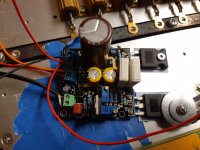
MEANWELL 50 VA 10000uF - Album on Imgur
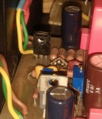
This is the capacitor soft start. I forgot to write the values. The first resistor to the red wire is 1R 7W. The second is 6R8 7W, The second neeeds to be tweaked. When the relay is on the 6R8 becomes near to zero ohms.
Not a bad result. Both the LF and 67 kHz nearing the noise floor. The absolute noise floor is about 20 dB worse than a good linear supply ( LD1084/LM317 ).
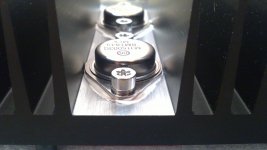
Today I soldered Hitachi's transistor 2SC4934 into a jlh amplifier (position Tr3), ft is 350MHz, hfe 400-800, cob 3.5pF at 30V. This is another of the fast video transistors I've tried as a Tr3 that sounds pleasantly surprising to me.
It may lack a bit of attack and precision like the 2SC1941 or 2SC2682, but the amplifier with it is very comfortable to listen to, I would particularly point out the lower part of the sound spectrum that really sounds powerful for such a small amplifier.
It may lack a bit of attack and precision like the 2SC1941 or 2SC2682, but the amplifier with it is very comfortable to listen to, I would particularly point out the lower part of the sound spectrum that really sounds powerful for such a small amplifier.
Attachments
From what I built that's a good move. I had a gain of 450. I had to add 33pF base to collector. I have 2SA970 2SD756 and 2SB716 I could try. The distortion was 0.03% at 10kHz 5 watts. Outputs were Indian 2N3055 E.
From what I built that's a good move. I had a gain of 450. I had to add 33pF base to collector. I have 2SA970 2SD756 and 2SB716 I could try. The distortion was 0.03% at 10kHz 5 watts. Outputs were Indian 2N3055 E.
The 2SD756 and 2SB716 have an even lower cob than the 2SC4934, only 1.8pF at 25V so they may need some compensation. Unfortunately I failed to get the original 2SD756 for the test so I would be interested in the results.
I listened to the amplifier all night with 2SC4934 and I can say that the sound is great, for my taste maybe too nice and pleasurable, I wish there were more attack, but overall it is a good choice.
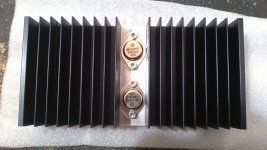
JLH looked at MJ3001 as the bottom output device retaining 2N3055 as the constant current device. He doesn't really say if he liked it. He does say it measures better. If a class AB amplifier the JLH class A probably would be quite poor and would need fast devices to work to a mediocre level. The fact that the JLH never fully swiches off allows slower devices. Where it might fall down is finding enough current from the input stage to drive the circuit ahead of it. Theory then and even now is transistor amplifiers work as transconductance amplifiers. This believes that forcing current amplification works best. If measuring the voltage deviations at the base of the next transistor it would look like a distorted triangle wave from a pure sine wave input. The output of the VAS for example will miraculous seem perfect at the output. I always had doubts. Making the impedance matching of stages better than typical is worth trying. IM distortion being the likely improvement.
Watch out for fake Japanese transistors.
Watch out for fake Japanese transistors.
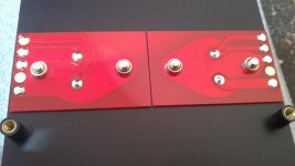
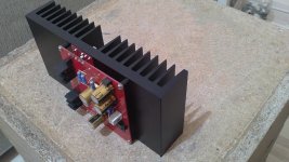
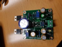
I have built two more versions of this amp and done some basic measurements. One is a TIP41C version from Zerozone, and the other a noname (Sen yuan) kit that I found out had mosfet outputs after I got it..
TIP41C Zerozone: Measures ok, high load impedance and high(ish) supply voltage improves distortion measurements. Seems to be happiest around 0,7-0,9A. Nothing special when it comes to measurements, and have not listened to it yet.
FET output version: Actually a little bit better in measurements than the one above with low impedance. I actually got lower distortion at 5,6ohms compared to 8ohms.. Seems to improve whith higher Iq and higher supply voltage. Relatively low distortion in 5,6ohm, but nothing special at 8ohm compared to bipolar outputs. However, current seems rather unstable, it's jumping around for no obvious reasons, and lab supply limiter kicks in even if limit is a lot higher than Iq setting etc.
No oscillation problems etc noted even with square wave in and 0,5u cap in parallell with load. Some ringing on the TIP41-board, but not much.
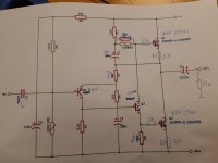
Attached some pics of the boards, and some 'notations' on schematics with some component values.
TIP41C Zerozone: Measures ok, high load impedance and high(ish) supply voltage improves distortion measurements. Seems to be happiest around 0,7-0,9A. Nothing special when it comes to measurements, and have not listened to it yet.
FET output version: Actually a little bit better in measurements than the one above with low impedance. I actually got lower distortion at 5,6ohms compared to 8ohms.. Seems to improve whith higher Iq and higher supply voltage. Relatively low distortion in 5,6ohm, but nothing special at 8ohm compared to bipolar outputs. However, current seems rather unstable, it's jumping around for no obvious reasons, and lab supply limiter kicks in even if limit is a lot higher than Iq setting etc.
No oscillation problems etc noted even with square wave in and 0,5u cap in parallell with load. Some ringing on the TIP41-board, but not much.
Attached some pics of the boards, and some 'notations' on schematics with some component values.
Attachments
Last edited:
Wien Oscillator using lamp - Album on Imgur
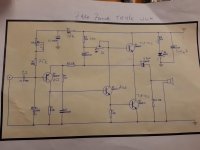
I tried a few low cost test oscillator designs. This one uses a very common aircraft lamp. It comes in many types . Type 327 ( not 327 LED ) is one example. I bought 10 for $5. Opamp is TL084 ( 74 ). Output is 1.7 V rms . It works better after 5 minutes warm up. I did try things like State variable filters. I doubt many will get them to work. Shame as the SVF I planned uses this lamp and distortion null. My test gear works to stage two. I could imagine distortion is about - 100 dB third harmonic. NE5532 might be better. Look for instability with that op amp. It is interesting to note the oscillator has to be good to -100 dB to test a JLH. I have to guess the second harmonic to be below - 80dB. The 100 R with the lamp is to try to reduce second harmonic. If going too far the AGC effect is lost. TL084 has a resistor current limiter. Ideal for this application. A 1938 idea. It is autormatic that lamp plus resistor is 180R when working. I would imagine the load is about the most a TL084 can give.
If you go to Ti Filter Pro you can improve the filters. You will need a remarkable op amp to do better. I did invert a stage. Yes it was better ( 3 dB ). Everything here is so as to say " Ah , that's how he did it ". 1.6 Khz is to use 10 nF 10 K . The 10 nF mylar 5%. If stage 4 is varied it is the basis for a signal generator ( 10K/10K can be changed ). Sorry for wrapping the circuit into the spare space.
I could imagine bipolar current sink and fet voltage amplifier could work. Its by negative feedback it drives the load. In theory the current sink might have close to zero distortion. Value guys won't touch bipolars. Morgan Jones loved them. His notes on valves with active anode loads is very good reading. Some second harmonic might be Early effect.
I replaced the TIP41C outputs with 2SC5242 (100% genuine) on one of the zerozone boards, and it looks promising. Distortion is clearly reduced (THD/IMD abt 10dB lower), and it also seems stable without any compensation added. There is actually no visible ringing now with square input and the 0,5u parallell with the load, there was a little overshoot and ringing with the TIP41C.
The distortion is still not as low as the zero zone PNP boards, but better than a standard JLH with MJ15003.
A 'hybrid' would be an interesting idea.. FET & bipolar, but I'm a bit reluctant to play with the FET-based boards, because traces are hard to follow on them since the PCB's are black. I asked for a schematic, waiting for reply..
Last edited:
Have you thought of finding the closed loop gain sweet spot..One would play with the lower feedback arm resistor. In theory half the gain half the distortion. Some say it creates higher order distortion. Not true. If the spectrum analyser has limited dynamic range it tends to show what wasn't seen before. A bit like zooming in. Making the gain higher should improve stability. An interesting variant would be a gain of two. The preamp would be very comfortable if asked to give up to 5 Vrms. The Idea I had was actually an op amp with SE class A output stage. This might be one transistor and one resistor. Into 40K plus it should be fine and drive headphones. 1 Vrms 32R and 6 Vrms lightly louded. I built a two transistor preamp with op amp type gain setting. It exploits npn pnp opposite curves to get reasonable distortion. I must publish it some time. I wasn't sure if it was better than an op amp. Sometimes simplicity goes further than it should. It measured about like the JLH. MC33078/79 my favourite op amp. I suspect gain of two not ideal for them. Gain of one incredible as is ten or even one hundred.
It's fascinating to realise that the 4 transistor JLH tests the test equipment to measure it. The story I know is Rosen describing measurements of 16 bit digital systems. 6.0206 dB per bit. 96 dB, Rosen speculates that the measuring system must be 20 dB better. He devises a State Variable filter to do that. Various cut down versions exist which need additional filtering usually. The Analogue Cookbook version very good.
Let's take the JLH as 0.05% thd. That's -66dB. Thus we want -86 dB. My design in 5777 might just do that.If the resistors change to 1K6 we have 10 kHz. Make the primary resistance 16K with optional 1k8 we have 1/10 kHz.7 pin DIN plug and socket being a low cost way to do it.Measurements of reasonable value up to 30 kHz are possible. If so I would use circa 3 nf 51K etcetera. 1 kHz and 10 kHz prime. If you see 0.1% the at 30 kHz be happy. You will see I kept every thing I could the same.
I choose TL084 as it is commonly used and very resistant to abuse. It has a most detailed set of graphs. For example it shows my 3.5 Vrms into 400R is realistic and has one volt headroom. If you simply bank the op amps it often works. I can't think of another that does. Resistor current limiting and JFET input allow that. One idea I like is Tl072/82 stage 1,2 and NE5532 stages 3,4. Tl084 is 0.003% thd gain of 1 at 6 Vrms 10 to 10 kHz. Elektor got about -96 dB at 1 Vrms 1 kHz from one. As far as I know Tl074 is a lower noise selection. BTW. Someone asked me what simulation I used. No, it's real on strip board. +-12 PSU using lm7812 in battery like connection with two bridge rectifiers. Like an all npn output stage.
- Home
- Amplifiers
- Solid State
- JLH 10 Watt class A amplifier