Thanks - hadn't seen that one.This link is to an interesting contrast of views on the topic, published as a "conversation" in Audio Express magazine quite a few years ago and we find this is no simple matter . Jan Didden also makes his views on the topic known. Musicality and Distortion: A Conversation | audioXpress

I'm also reminded that Lynn Olson took the view that different styles of music match different distortion profiles: he's a fan of massed voice and orchestra which is much less tolerant of a bit of 2nd (due to the IMD products) than, say, a solo instrument. Rod Elliot did some interesting work in 2012 on this and, in his usual way, drew some strong conclusions from listening to test tones.
Last edited:
I have been messing around with current and balancing between transistors on the white boards, and listening and comparing. They sound nice and a little bit laid back, but when I compare with the PNP boards, they are just on the next level. I guess it's a matter of preference too, but for me I definitely prefer the PNP boards. I listen to a lot of rock, and pay a lot of attention to the transients from drums and bass. Preferences might be different for other music and other ears.
Both versions are converted to floating ground and fed by 19V laptop bricks.
The white NPN boards have 15003 outputs, and the other transistors are standard. Feedback resistors are modified with 'sublimed' values (lower resistance values).
The PNP board components are as delivered except R25 replaced with a 220ohm, and R26 tuned with FFT for maximum cancellation/minimum IMD, with Iq ending up at just over 1A.
The biggest subjective difference between the two is in the low register, but there is still a small advantage in the treble too, to my ears. For the moment I don't want to mess with these, possibly making them worse. I would even dare to recommend the boards for those looking to try something different in JLH-land 🙂
However they need to drive speakers that are a fairly easy load with only 1A Iq. I have been doing most of the listening on a pair of DIY speakers with Vifa P17 & modified Monacor DT300, a budget side project that really surprise me with their sound together with this amp. Need to get some friends over to listen and see if they agree with me.
Last edited:
When the transistors have high gain, I tend to lower the closed loop gain. When the transistors have low gain, I tend to increase the closed loop gain. This is to get the right 'balance' based on taste. Perceived distortion versus musicality.Need to get some friends over to listen and see if they agree with me.
I have been looking in the thread from the start, trying to pick out the 'needles in the haystack' 🙂 Maybe half way through at the moment.
Found a spice-model by Bigun that I tried to get running, but I could not get it to work, adding models etc.. I'm a novice.
I borrowed a good scope from work over the weekend to look what is on the output in the 'real world' with speakers, cables etc.
I have now connected it on the PNP JLH, with fast outputs and saw something around 2GHz, not constant, but kind of a pulsating oscillation.
However, after some testing, I found that the old plasma sitting close to the amp was the source. When I turned it off, the noise was gone. Moving the input cables & usb sound card around did not seem to do much.
There is still some sporadic, low level swings in the 70MHz range, but those seem to be present on the source too (sound card). I have a long USB cable to the sound card, so maybe it's acting as an antenna.. or the noise is from the laptop in the other end.
I guess a filter cap on the input could be a good idea to get rid of those. I'm not sure about the pickup from the TV, if it comes through the input or the speaker cables, but that one was a bit disturbing to see.
However, I'm happy to see that the switched supplies (laptop bricks) don't seem to make any trouble, that was my main concern from the start, and the reason to have a look.
These zerozone PNP boards have no HF filtering of any kind, not RC or coil on the output, and no RC on the input, so I guess it would be wise to add something.
Member
Joined 2009
Paid Member
I've seen similar things in my hobby room - there are many sources of environmental noise these days. Just as the oceans fill with plastic waste, the rivers with hormones and chemicals, the air with particulates... the 'ether' is being filled too. Many of the old designs that we admire for their simplicity were from an era when designers did not have to cope with so much environmental EM crap. I suspect some people, myself included of course, have avoided dealing with it in the name of 'purity and simplicity' but we do so at our peril. Adequate design practices today require us to consider external factors on our audio.
Yes, I definitely have to do something about this. Ordered some R & C to be added. Maybe it could even explain why sometimes I thought it did not sound so great, but the next day it was 'normal' again.. could have been the TV was on.
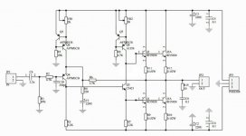
Anyway, I'm slowly putting together the dual output/dual supply boards, and the first measurement I did was not so impressive. Especially with 4ohm load.
I would like to be able to tweak the balance between the output transistors on this one too, but not sure how/if it can be done?
Schematic attached, hope somebody can point me in the right direction.
Attachments
I found that the old plasma sitting close to the amp was the source. When I turned it off, the noise was gone.
Likewise I have found flat screen monitors seem to radiate noise in the 19 to 20KHz region when looking at spectrum scans.
Unfortunately, this is a bit of a 'Catch-22', no monitor, no spectrum view 🙁
Regards
Mike
You may not need 19" or more of monitor screen to see all that you need. A low power laptop or Android tablet may be just fine for spectrum graphics figures etc. and will likely emit much lower radiation if much at all. Even kids often have more than one of these so they're not hard to access or buy, if need be.
Hi there,Anyway, I'm slowly putting together the dual output/dual supply boards, and the first measurement I did was not so impressive. Especially with 4ohm load.
I would like to be able to tweak the balance between the output transistors on this one too, but not sure how/if it can be done?
Schematic attached, hope somebody can point me in the right direction.
in terms of getting the balance 'right', what I did was to measure the hfe of the output transistors and put those with the highest values in the lower position - obviously you have to do this for both channels so it means getting quite a few of the o/p devices to cherry pick from. This was the advice that JLH gave in his original article as a way to get the minimum distortion.
It would also probably be a good plan to implement the o/p pairs one at a time and get a feel for how the amp works and sounds before adding the second pair. I used MJ15003s on my version.
If you have them, a +/- 30 Volt @3Amp bench power supplyand an 8 Ohm dummy load would be very useful when testing.
Cheers
Mike
The balancing I was referring to was to adjust R1/R2 (ref to original 69 schematic) to cancel 2nd harmonics from the outputs. Not sure if the same can be done with the CCS version?
No bench supply with such high rating, but I have dummy loads and setup with Arta and sound card to measure distortion spectrum, and planning to compare one channel with 4 outputs, and the other with 2. Not a thick enough wallet to buy a load of (15003) outputs to chose from either..
Another question(for the other JLH boards I have): When it comes to filtering HF on the input, I was planning to use 4,7k in series and 330p to gnd.
However, while I'm slowly getting through this thread, I have seen other variants of this (plain capacitor to gnd for example), and also read that input impedance has influence on the stability of the amp. Should I just go with the 'standard' filter, or are there better options?
On the output I'm planning 0,1u + 10ohm to gnd (+ possibly small RL), and have seen no alternatives to this.
Last edited:
Often to reduce second harmonic is to reject the whole concept of this design. The idea is to have second above third. Douglas Self loves to get rid of second as statistically it is distortion. I couldn't agree less. Douglas rightly rejects certain distortions and how they got there. I think he believes if distortion is very low how it is made up is unimportant. Many do not agree with that. I dare say he doesn't mean that, it reads that way. 1% second and 0.3% third and 0.1 % fourth with 0.03% fifth could be a zero distortion sound to our ears.
Yes, but as far as I know know now, I prefer the sound when the 2nd is adjusted down. It has been at about the same level as the 3rd on the JLH boards I've been experimenting with.
The usual way to get that is to use a long tail pair input stage. If some second harmonic is wanted the LTP can be forced out of balance like in Naim NAP 140. One way that might have merit is using a complementary feedback pair input.. If that can be done without modification needs some thought. Rendarson Audio show how. The second harmonic should mostly be due to curve distortion of a single input transistor not corrected by loop gain. What some valve designers do is mix the distortions of triodes and pentodes. If the pentode has sufficient current reserves it is a practical solution. Predistortion as it's sometimes called has none of the problems of negative feedback. As each stage of a valve designs inverts at each stage even triode to triode distortion cancellation takes place. Basically the errors are mirror imaged. Some of this occurres in JLH. One way to reduce second harmonic is to use Quad ESL loudspeakers. KEF LS50 whilst not as good is a good attempt.0.8% from memory against 0.1% Quad. 3% is typical at levels where it's noticeable. To my thinking the coil leaving the mangetic gap is the cause.
This is getting too complicated for me.. adjusting the resistors on the 69 version was an easy task, but rebuilding the amp to something else is not what I'm after, just tuning the ccs-version a little to balance the outputs.. Or maybe rebuilding that part of the circuit to the 69 version and tune it as I did with the others could be an option, but I want to test it as is first.
Could adjusting the 2,2k for the lower outputs do this 'balancing'?
Could adjusting the 2,2k for the lower outputs do this 'balancing'?
Attachments

Last edited:
The great complication of the JLH is the current sink is on a knife edge of working. Massive performance advantages come from these sensible compromiss. It's like the balance factor of a single cylinder motorcycle that is then fine tuned to it's frame and mountings. The motorcycle has a dreadful problem we don't have which is every fourth part of the cycle is compression.
JLH I seem to remember says to measure all transistors and put the highest gain as the top transistor or current sink. I would love someone to explain the current sink. In theory the transistor gain is too low.
.
JLH I seem to remember says to measure all transistors and put the highest gain as the top transistor or current sink. I would love someone to explain the current sink. In theory the transistor gain is too low.
.
JLH I seem to remember says to measure all transistors and put the highest gain as the top transistor or current sink. I would love someone to explain the current sink. In theory the transistor gain is too low.
.
Hi Nigel,
IIRC it was the other way around in that the minimum distortion occurs when the higher hfe device is in the TR1 (lower) position.
On mine, adjustment of the distortion levels was accomplished by injecting a 1KHz signal in, looking at the attenuated output spectrum using ARTA and adjusting the Iq pot to the appropriate level.
I found that with multiple output pairs, the distortion percentage reading varies according the power output so the adjustment point is a compromise across the power output range.
The acutal way the amplifier work still seems to be a point of discussion - Geoff Moss wrote some thoughts on this here:
The Class-A Amplifier Site
Kind regards
Mike
Often to reduce second harmonic is to reject the whole concept of this design. The idea is to have second above third. Douglas Self loves to get rid of second as statistically it is distortion. I couldn't agree less. Douglas rightly rejects certain distortions and how they got there. I think he believes if distortion is very low how it is made up is unimportant. Many do not agree with that. I dare say he doesn't mean that, it reads that way. 1% second and 0.3% third and 0.1 % fourth with 0.03% fifth could be a zero distortion sound to our ears.
Unfortunately to believe harmonics are benign misunderstands non-linearity in a very deep way. Non-linearity invents new tones not present in the original by harmonic and most importantly intermodulation distortion. Intermodulation is really nasty whatever order as completely unrelated signal mush appears all over the audio band whenever a complex signal is present. THD is easy to measure, IM is harder, which is why we frequently use THD as a stand-in for measuring non-linearity even though IM effects are often the most objectionably.
Here's what happens to a set of 6 different pure tones (green) subject to 1% 2nd-order distortion (blue), and then another 1% 3rd-order distortion (red). Its a complete an utter mess of mush everywhere.

Note the IM products are all over the place, in vast numbers. This is the true nature of non-linear distortion.
Last edited:
.. It's like the balance factor of a single cylinder motorcycle that is then fine tuned to it's frame and mountings. The motorcycle has a dreadful problem we don't have which is every fourth part of the cycle is compression.
.
Love the analogy, I can relate to that! (been tweaking cars & bikes for a long time) 😀
I did some quick measurements on the dual output boards with ccs today. One board with a single pair of outputs installed, and one with double. I must say I'm not impressed with the results. IMD and 1kHz distortion spectrum looks worse than both the modified 69 boards I have. Nicely falling, but higher overall levels. Loading them with 4ohm makes distortion jump up abt 20dB. Funny thing is that minimum distortion is achieved with lower Iq on a 4ohm load compared to 8ohm, as long as it's kept away from clipping. Could it be overloading of the 'splitter transistor' causing this?
As it is now, I'm not impressed by those boards/amps, I'm thinking they are better for burning more heat (with double outputs), but not for producing better sound. I'm using BD139 as 'splitter' and MJ15003 as outputs.
Glad you liked the motorcycle analogy.
I understand Jean Hiraga lives in Lille France. I have family in Tournai it's near neighbour. I should ask a multual friend to ask to say hello. As I understand it Hiraga says There are two low distortion types. One has no distortion ( -120 dB ? ). The other has 0.1% thd with exponential decay of the distortion harmonics.He said it in translation many years ago and may not believe it now.
I supplied some KEF T27 tweeters for the experimental hearing dept of Oxford university. I asked how the ear worked. The researcher said the intrinsic distortion of the ear is about 30%. The brain knows this and processes the signal. He and I speculated that if the distortion of the hi fi is identical in harmonic proportions it will not be heard. Small out of sequence distortion will be heard.
The greatest fascination he said was a return signal from the brain to the ear. It required a 2 MHz bandwidth. The USA military have speculated about similar things.From my observation despite hearing loss the system speed of the ear doesn't fall away. People can infer information.I fitted a super tweeter to a friends speaker. It made a very big difference. In theory my friend and I can't hear it. We tested that and we couldn't as we are too old. I did search for an alternative explanation. My conclusion is we listen to waveform shape. That is assuming good hearing for the age. 10 kHz is realistic for the 60 plus age group. 12 KHz where it vanishes. The speaker is titanium full range. It sounds nasel. With the super tweeter the sound is open. No attempt was made to change the titanium unit. Although I haven't tested it I would expect a better square wave at 1 kHz. It sounds like it might be able to do one. Most speakers can not do square waves.
I am glad I mixed up which transistor needs the higher gain as it needs saying either way. What I find hard to understand is the 1 amp of standing current can be created by such a small base current. The nearest similar current settings is a primitive class ab. I like that it works so well without complexities.
My daughter who is autistic went to the university hearing dept. They think some Autistic people have better hearing. She has remarkable hearing. Unfortunately she hears things she shouldn't and repeats them. She can be in the far end of the house behind a closed door and hear conversations.
Nigel,
I find that research result very interesting. Thanks for posting it and do you have any links to the detail. I may remove the low-pass filter (47K/330pF) and see if that makes any major difference.
I built my amp about 10 months ago: it is what I would describe as 'bright but not fatiguing' but that could also be the speakers which are B&W Matrix 801 Mk III which are somewhat ruthless in their accuracy. I have done a side-by side comparison with a Chord and some Quad power amps and invited several people to listen to them (a few of them much younger than me and so having 'younger hearing'). All of them prefered the JLH - common comments being along the lines of "Removing a curtain from in front of the speakers and " Much more detail" particularly on voices and piano: Cat Stevens' 'Morning has broken' is a really good test for piano diction.
From what I remember, when I had them on the bench, 2nd harmonic was about -100dBFS in ARTA for an input of -6dBFS (the sweet spot on my sound card) and 3rd was about 6dB below that. The remaining harmonics were down in the noise which was about -135dB'ish except for a 50Hz lump at about -120 or so, and I do like the fact that when the amp is on, one can put an ear to the speaker and hear absolutely nothing. 🙂
The amp was running at about 3.5 amps Iq with +/- 39 volts rails - again from memory though.
I am currently learning to use LTSpice and, as a learning excercise, I plan to build a model of the amp so as to compare actual with theory.
Rallyfinnen, can you vouch for the source of the transistors you are using? The reason for me asking is that MJ15003s are one of the most common devices to be 'faked'. There is a good article about this on Rod Elliott's site.
Also, what is the power supply you are using? Have you tried a Capacitor Multiplier for example?
Kind regards
Mike
Last edited:
- Home
- Amplifiers
- Solid State
- JLH 10 Watt class A amplifier