Yes , you understood exactly. You can apply an adjust in series with a potentiometer . The adjust for the bias and with the pot. you adjust the shunting resistor the one which parallels the base emitter. This resistor will balance the gain with the lower one . If it requires too high value than you have very little left for the bootstrap capacitor and the supply. If such occurs, it means the upper has too low Hfe vs the lowers . The IMD and even order harmonics have the same cause , but what concerns sound, the story if different. To give an example, the revered SHURE V15 type 5 most expensive in 80's used mainly by radio station, recording studios has 2.5% 2nd order harmonic 0.5% 3rd and IMD of 3%. The lower output as it is driven by emitter follower works with its Ic/Vbe function . The 3055A having decreasing Hfe above 200ma results very linear Ic/Vbe transfer function . Once the RCA datasheet showed how linear it is in linear scale . Motorola shows in nonlinear one not easy to see . This why I advise you you keep the lower the 3055A . JLH himself preconizes to use of different Hfe s as the two outputs function differently. As 3055 is of low Hfe and speed ,20Khz, you will not have any difficulty to match the upper one.
To sublime it first apply the current mirrors to bias the input transistor 2ma instead of 200ua , and listen the difference.
To sublime it first apply the current mirrors to bias the input transistor 2ma instead of 200ua , and listen the difference.
Thank you for the reply. I think I did not follow everything you wrote.. I think it would be easier for me if you used the component numbering from te schematic.
Anyway, based on how much I did understood, I increased R8 to 270ohm, and re-adjusted it for lowest distortion. Now the Iq is around 1,5A.
I also added a 0,3mH coil before the 15mF cap on the supply, and added a low ESR 2200uF cap in parallell with the output cap to see if it would do something to the bass.
This time I adjusted the offset pot for lowest distortion at high output. This meant that the distortion on low output was slightly higher, but I think that's a fair compromise. I guess that has something to do with the linearity of Q4 and in what range it is operating? I guess the modified current in this transistor would affect this too?
When it comes to the outputs, I have a feeling the supplied transistors were not good. Very big variations in hfe, and they are marked ST, but I'm not sure they are actually ST either..
When it comes to distortion, I have not done any real experiments to hear what I prefer. However I have a feeling that distortion sounds better on acoustic recordings with not too much going on at the same time (acoustic guitar is a good example). With more complex music with a lot of sounds and instruments, with various reverbs and effects added etc, I have a feeling that distortion makes the sound less clear (IMD i think). One thing I started to listen to is the 'black background' to reverbs etc, and that with a lot of instruments they can still be separated.
I know a lot of distortion is added by speakers too, and for a long time I did not worry to much about amps for this reason, but lately I have listened and played around with many amps, and there is a clear difference, even if distortion levels are well below those of the speakers. I have measured amps that were really clean too, but did not like the sound. Makes no sense to me, I only know I can hear it.

For some reason, after the changes I did yesterday, I found the sound is now 'mediocre' compared to 'good' before. I would think it has to do with the pot adjustments and distortion profile.
Maybe a slight improvement in bass though, probably from the extra cap on the output.
I must say I'm reluctant to put back the 3055's, because of the suspected low quality.. Maybe I could take the two with the higher hfe and use them in the lower positions..
Maybe a slight improvement in bass though, probably from the extra cap on the output.
I must say I'm reluctant to put back the 3055's, because of the suspected low quality.. Maybe I could take the two with the higher hfe and use them in the lower positions..
If you the Hfe curve of 3055A you find it very dirty component , it is this that makes it excellent for this application. Use on the contrary the lowest Hfe , because the Fr =Ft/Hfe and you get with highest frequency response which nominal value is 20Kz.For some reason, after the changes I did yesterday, I found the sound is now 'mediocre' compared to 'good' before. I would think it has to do with the pot adjustments and distortion profile.
Maybe a slight improvement in bass though, probably from the extra cap on the output.
I must say I'm reluctant to put back the 3055's, because of the suspected low quality.. Maybe I could take the two with the higher hfe and use them in the lower positions..
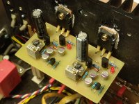
This is the latest version of the voltage regulator for my JLH69, for some wonderful wonder OS-CONs work well in the controller, I usually only use them in digital but they are OK here too. I also changed the drivers, I put in transistors with bigger fT and smaller cob.
The sound has changed again, and it's better again.
I'm going to draw a complete power scheme with regulators, positive and negative when I do all the testing and find the best components and it would be great to try this regulator with Hiraga in A class because it's the next amp I think to do.
The sound has changed again, and it's better again.
I'm going to draw a complete power scheme with regulators, positive and negative when I do all the testing and find the best components and it would be great to try this regulator with Hiraga in A class because it's the next amp I think to do.
Attachments
I have been soldering on the board with dual outputs (https://www.diyaudio.com/forums/solid-state/3075-jlh-10-watt-class-amplifier-560.html#post5957967)
I powered one with some odd output transistors I had lying around just to see how it works. Now, there is some oscillation around 2GHz..With single outputs when I touch the driver transistor (BD139), the oscillation stops. If I connect dual outputs, the oscillation is damped and sometimes stops completely when I touch the same transistor.
If I decrease Iq, the oscillation also stops.
Maybe it's a bad PCB design, maybe I have the wrong choice of transistors? I also have the outputs on short twisted leads(C & E twisted, base only parallell to the other two), since they are the wrong package to solder directly to the PCB..
The RC on the output is missing, because I'm waiting for the components.
Is there something I could try as an easy fix to get it stable?
I will try some other output transistors just to see what happens, but since I don't understand the details of the design, I'm asking for some pointers..
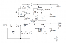
Transistors are:
Q1, Q2 KEC D1047
Q3 BD139-16
Q4 a970
Q5 a970
Q6 a970
Q7 a970
Q8 BD140-16
I powered one with some odd output transistors I had lying around just to see how it works. Now, there is some oscillation around 2GHz..With single outputs when I touch the driver transistor (BD139), the oscillation stops. If I connect dual outputs, the oscillation is damped and sometimes stops completely when I touch the same transistor.
If I decrease Iq, the oscillation also stops.
Maybe it's a bad PCB design, maybe I have the wrong choice of transistors? I also have the outputs on short twisted leads(C & E twisted, base only parallell to the other two), since they are the wrong package to solder directly to the PCB..
The RC on the output is missing, because I'm waiting for the components.
Is there something I could try as an easy fix to get it stable?
I will try some other output transistors just to see what happens, but since I don't understand the details of the design, I'm asking for some pointers..
Transistors are:
Q1, Q2 KEC D1047
Q3 BD139-16
Q4 a970
Q5 a970
Q6 a970
Q7 a970
Q8 BD140-16
Choice of transistors.
There is no frequency compensation capacitor in the original 1969 and 1996 amplifiers. By design according to JLH in his book on Valve and Transistor Audio Amplifiers the dominant pole is set by the fT of the output transistors - about 2.5MHz with 2N3055 epitaxial base types which he recommended for the 1996 update.
Putting your finger temporarily on the BD139 adds just enough capacitance between the collector and base causes this device to take over the dominant pole.
For a stable amplifier the dominant pole needs to be at least 10 times greater - that is lower in frequency - than any other natural pole in the circuit.
Thus you don't want your poles to be too close together as these would be with BD139 and KEC D1047 due to fT figures of about 40 MHz and 15MHz respectively.
By comparison the figures for 2N3055 and 2N1711 are 2.5MHz and 70MHz.
The situation with Class A amplifers is different in that relatively slow devices like 2N3055 are fast enough. Faster devices are the rule with Class AB you have to factor in switching delays which slows the response and frequency capability.
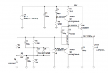
I use fast transistors in my version and there are no oscillations, only with 2SC1941 I got instability and by adding a C4 of 4.7pF I removed it. Nigel Pearson recommended the addition of C4 to me because he too had the same problem with BC337-16. In my JLH69 BC337-16 worked without oscillations and without any compensation.
I currently have a 2SC1941 in the amplifier, which has a fT of 100MHz at 10mA and the outputs are at 2A 60MHz. Instead of 2SC1941 I used faster transistors such as sanyo 2SC3953 where fT is 280MHz or toshiba 2SC3423 with fT of 240MHz without C4 and without oscillations.
The 2SC1941 only has a Cob at 20V below 2pF of the transistors I tried and only it oscillates. hFE for all transistors was between 200 and 400. Outputs have an hFE of about 160.
For the input transistor I now use toshiba 2SA1312 which is 2SA970 but in SMD and certainly not a fake.
Attachments
Sorry, I'm too slow to understand how this works.. I tried Self's book too, but I still don't grasp it..
Maybe I could try the bypass cap as grunf suggests, and that would make it stable?
Oscillation is not crazy, abt 50mV peak to peak.
Maybe I could try the bypass cap as grunf suggests, and that would make it stable?
Oscillation is not crazy, abt 50mV peak to peak.
Sorry, I'm too slow to understand how this works.. I tried Self's book too, but I still don't grasp it..
Maybe I could try the bypass cap as grunf suggests, and that would make it stable?
Oscillation is not crazy, abt 50mV peak to peak.
If your intention is to build kokoriantz' sublimated amplifier do so with the transistors he chose - he knows what he is doing. All the same leave out the 220 pF optional lead capacitor.
For an explanation as to why you should do that, read the original Wireless World April 1969 article for the Simple Class A Amplifier by Linsley-Hood.
You will find this in pdf format at ~ Scanned and cleaned up Wireless World Articles ~
The relevant piece is in the first paragraph under the heading "Stability, power output and load impedance."
There is a post -script in December 1970 issue of Wireless World in Snook's list. It is mentioned therein that the small signal frequency response extends flat to 2MHz within 1dB. MJ480 output transistors had an fT of 4MHz so with 15MHz devices the frequency characteristics could be expected to extend that response somewhat.
At 2MHz the impedance of a 220pF capacitor is 361 Ohms so if an out phase high frequency signal is presented by the speaker load due to delays. This will take the short cut route to the inverting input.
Above 2MHz you can expect a proportional decrease in the impedance of a 220pF capacitor.
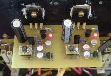
I have a standard white PCB JLH 69 for the sublimed experiments. This is the dual supply, double output PCB. I only bought this as a plain PCB to play around with and see what kind of sound it will make, hoping to use mostly components I have from before. Kind of a learning process with amps for me. Learning to understand, and learning which ones that sound good to me. Many end up in the scrap box due to bad sound, or mistakes from the builder.. 🙂
Looking at slower transistors, I saw TIP33 could work if I want to go cheap? But maybe single pairs of 3055 or MJ15003 will handle the same power, and give better sound due to easier load on the driver transistor? I would however like to try double outputs too, and it gets a little bit expensive buying 8pcs..
Looking at slower transistors, I saw TIP33 could work if I want to go cheap? But maybe single pairs of 3055 or MJ15003 will handle the same power, and give better sound due to easier load on the driver transistor? I would however like to try double outputs too, and it gets a little bit expensive buying 8pcs..
Last edited:
I have a standard white PCB JLH 69 for the sublimed experiments. This is the dual supply, double output PCB. I only bought this as a plain PCB to play around with and see what kind of sound it will make, hoping to use mostly components I have from before. Kind of a learning process with amps for me. Learning to understand, and learning which ones that sound good to me. Many end up in the scrap box due to bad sound, or mistakes from the builder.. 🙂
Looking at slower transistors, I saw TIP33 could work if I want to go cheap? But maybe single pairs of 3055 or MJ15003 will handle the same power, and give better sound due to easier load on the driver transistor? I would however like to try double outputs too, and it gets a little bit expensive buying 8pcs..
It has to be remembered most transistors of the 1960s would struggle to complete with any modern transistor. I remember TIP3055 being what we all had wanted. It seems it is not really 2N3055 exactly. About 4 times faster. BDY56 the dream version. I believe Cricklewood Electronics London have them. Beautiful in the early Naim amplifiers.
Slewing distortion when a class A amplifier is less likely as the outputs never switch off. When class AB It's like you are on a ladder with 2 metres missing. Somehow in zero time you have to climb the missing part smoothly. When class A the ladder is complete an no fast precision movement required.
One could argue for high speed in the PSU.
The driver transistor should be very high gain. This can reduce distortion. Mine was gain 400.
It could be argued that NAD 3020 can considerably outperform the jlh for one reason. This is because the NAD power supply is faster whilst the NAD has slightly better distortion. I have found even if the NAD power supply is reduced to 2000uF it has no obvious hum modulation. A NAD can make an excellent preamp and is an excellent amplifier to compare with. The NAD genuine RCA 2N3055 have wonderful sound. I believe they are the E version not Believe it or not bass can sound more powerful when the PSU capacitors are minimal size. It's to do with optimum charging. Modern smaller capacitors have higher ripple current so can be an option. When the jlh this option is more restricted. There is an option which is an fet capacitance multiplayer. It can offer the speed. Oscilloscope required as oscillation is possible. The NAD is a very remarkable AB design with no obvious defect against a jlh. It is unlike any other amplifier. Nothing the RCA design said to be many.
...vs ripple induced intermodulation distortion.Believe it or not bass can sound more powerful when the PSU capacitors are minimal size. It's to do with optimum charging.
about a decade or so ago someone finally cottoned on that class AB guitar amp P/S sag didn't just play games with gain, it also introduced modulation from the ripple current. So your guitar combo should sound different when you cross the Atlantic.
You can read about it at ampbooks.
Just another way we can mess up sound reproduction.
I've said at least a dozen times in this thread that I'm gunna do a choke input supply for a JLH 😱 😱 😱 but maybe one day. Current solution is a by-the-books regulated supply, which is electronically quiet but mechanically noisy.
I learnt this from Nain Audio. A reviewer questioned the modest capacitors used. Naim provided his suggestion. He had to agree their version better. He speculated that there would be an optimum symbiosis with the transformer. If the transformer is small perhaps the sound needs a smaller capacitor. The reviewer called it muscle bound. What usually sets the parameters is ripple rating. My rule is the capacitors should have at least 50% surplus rating. My NAD experiment at 5.4 amps.
In theory if the ripple doesn't decend into the music the amplifier should remain uncoloured. 5 watts is typical of average loud sounds. At 20 watts the major distortion is our ears. We might even like a bit of grunge.The Quad 405 always sounded puny. Probably because it didn't go grungy.
The main thing is experiment. A NAD 3020 would make a very good preamp and matches the jlh in style of sound. The NAD JLH combination should sound better than the NAD alone. Mostly because the preamp is then not sharing a power supply. Don't be surprised if at first the NAD alone sounds better alone. I prefer the NAD over a famous class A design costing silly money.?
When I built my jlh experimental amplifier it was a junk box special. Indian 2n3055s. BC 327/337-40. An oversized heatsink of 0.2C/Watt. The PSU a very standard smps by Meanwell that stretches to 28V at 50 VA. I built the 1969 original without any PCB. Distortion was exceptionally good. It was 0.03% 20 kHz and fell lower with frequency. I fitted 1 ohm and 1000uf to the output of the smps. This measures current and is a 160 Hz filter. The smps slightly objects to this on start up. These were not the choices of deep thought. The first thing I had to hand.
I was rather surprised how reasonable this was. So much so it should be a serious possibility. A true class A amplifier might be ok with this. As it has a relatively constant current consumption there can be no camouflaging power supply defects. If it measures badly it will sound bad. Class AB have fascinating complexity here. Slewing and PSU problems. AB types are close to miraculous.
As smps are cheap they are worth trying. Like the NAD it will challenge your theories.When swapping output transistors you might actually be observing amplifier stability. Reading this thread I assume most people do no measurements.
If someone has information on freeware spectrum analyser it would help this thread. I know ones even I can't afford. Anything of 80 dB dynamic range should be enough. Even 60 dB for defects. My old Ferrograph was what many used in the day. Doubt I would know how to use it now. The JLH sine cosine wein bridge is a nice test oscillator.
Are you looking for a spectrum analyzer for the audio band for distortion measurement?
If so, a decent sound card (for 80db even a built in sound card should be enough) and some software will solve the problem. I use the ARTA demo version, and there is also REW which is free.
If so, a decent sound card (for 80db even a built in sound card should be enough) and some software will solve the problem. I use the ARTA demo version, and there is also REW which is free.
That was my thinking. At some point guessing has to stop and measurements made. A spectrum analyser that shows distortion and noise is essential. Any sound card should be good enough. I have an Elektor oscillator circuit using 28 v 40 mA lamp plus Tl074 giving -108 dB at 1 kHz. If batteries used £5 to build. Less if you have a tin box to put it in.
My engineer neighbour was discussing the Bassman amplifier a few days ago for another reason. I can't wait to tell him about it's power supply in the link supplied. I think if AB the mains transformer can work as an energy store. The Carver amps exploit that concept. Class A amplifiers have saturated supplies that follow different rules I suspect an RC last stage worth trying. When AB power transistor decoupling and wiring do an excellent similar job.
My engineer neighbour was discussing the Bassman amplifier a few days ago for another reason. I can't wait to tell him about it's power supply in the link supplied. I think if AB the mains transformer can work as an energy store. The Carver amps exploit that concept. Class A amplifiers have saturated supplies that follow different rules I suspect an RC last stage worth trying. When AB power transistor decoupling and wiring do an excellent similar job.
Using too high a feedback capacitance can cause oscillations it is supposed to suppress!
I'd agree that 220pF is too high, but I've only found a capacitor necessary when using e.g. MJL3281A outputs with high fT. A value around22pF is more like what I found.
If you are having trouble with oscillations with low frequency devices (like 2N3055/MJ15003) you might find that the circuit needs a low input impedance. I've not built the 1996 version but using high input resistances can change the frequency response of the input stage dramatically when open circuited,creating an additional phase lag. A 100pF capacitor across the input base to ground might be enough to keep the impedance down at HF and the frequency response high, keeping the phase shifts under control
Strangely I have a PNP version from ZeroZone with SA1216 outputs and 2sa970 as driver, and that one seems stable without any extra capacitor.
- Home
- Amplifiers
- Solid State
- JLH 10 Watt class A amplifier