😀 hello erifce, l looked for your schema on the page you mentioned but l must be getting old and short sighted and couldnt find it only a vague reference to tne esp pages and the doz [ ya know l'm blind in one eye and cant see outa the other ] could you post your drwing or schema again please for this old gringo😀 cheers TC
] could you post your drwing or schema again please for this old gringo😀 cheers TC
and the pcb mirrored.
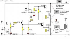
please before constructing it read the rod´s article about this amp, otherwise you can blew up almost instantaneously.
this is the rod´s page :
http://sound.westhost.com/project36.htm
i repeat, please read the whole article before building the amp specially if this is your first amp.
thanks to Elvis rakich por the pcb layout , and to master rod for the amp itself.
cheers.
Attachments
😀 trust a lowlander to chime in and talk nonsense, typical dutch know it all, how would you know if l'm not a gringo?............. maybe the frost has addled your brain.... stick to your edam and rollmops, things you really know something about [ this aught to make the moderators happy, hello si- bin here l come again]😉 cheers all and thanks erfice l will read all of rods treatise on the doz, but where is the multiple bd 139's on your schema?, thanks againTC
hello, this is the 4th and last time i say the same thing,
the bd 137 does NOT appear on the schematic nor on the pcb. to know details on how i have paralleled those devices please report to my comments on page 114 (wiring by air)
cheers
the bd 137 does NOT appear on the schematic nor on the pcb. to know details on how i have paralleled those devices please report to my comments on page 114 (wiring by air)
cheers
Re: Thanks
I've ordered once, had them picked up (thanks mercator). Not everything shown is always in stock.RKH said:Paulb,
Thanks. Do you do a lot of business with them?
qwad said:stick to your edam and rollmops
Actually, the rollmops is in my ear.
It is winter over here and bloody cold, you tropical you !
Now, if someone would do an output stage layout for those number of BD's that we could all just snatch off here !
hello,
there is no layout for the bd137, it is much more simple to simply solder electric wire beetwen them, its fast an easy and no hum!!, just put some wire soldered to each transitor plus the resistor on the emitter...
Simple as Simple does!
good soldering hehe
there is no layout for the bd137, it is much more simple to simply solder electric wire beetwen them, its fast an easy and no hum!!, just put some wire soldered to each transitor plus the resistor on the emitter...
Simple as Simple does!
good soldering hehe
I am intrested in building a JLH amp as my first amp. Is the DoZ amp basicly the same thing or should I just build the 1996 version of this amp?
Could someone post a culmination of what knowledge was gained over all these pages on this amp?
Could someone post a culmination of what knowledge was gained over all these pages on this amp?
Dear DJNUBZ, can't leave you hanging out there by yourself all day can we? I think that after all this time (24hrs) the answer is "No", you aren't likely to get "The Reader's Digest" version of this thread any time soon. I recall that sometime in the last few months one guy 'fessed up to reading it all the way through! Still that was in the good old days when it was only about 1,000 posts long. But all is not lost. You'll find that in this thred there is consistent reference to the site run by Geoff Moss in the UK. It is pretty much dedicated to the JLH Class A amp'. Now it doesn't follow up every tangent that has spun off this thread but it does contain the condensed wisdom that is needed to bring about a practical realization of both the 1969 and '96 version. I'd start there. I think just putting "class A amp" in Google will get it but this might be quicker. Try www.tcaas.btinternet.co.uk/index.htm#index
welll,
if we belive nelson pass : the doz is a version of the jhl amp with an unflattery name
if we belive geoff moss : the doz is basically the same amp with a transistor added ton better control the quiescent current
if we see the page of rod elliott ( the creator of the doz) , the page is full of doz references...
so the answer is YES
both the doz and the jlh have the same topology.
as a first project it could be a little dificult, but anyway doable...
high freq oscillation at negative peaks
I have soldered a JLH 69 cct on a protoboard. Runs at 1.7A, 40V single supply. Transistors are : 2SA970, BD139, MJ15003.
With single output transistor pairs (tr1 and tr2), the cct works nicely upto 35v peak to peak output.
As I found tr1 and tr2 are getting too hot, I parallel a second transistor to each of them. At low output swing, about 10v peak to peak, the waveform is very clean. As the output increases to over 15vp-p, there is a RF oscillation superimposed on the negative peak; the frequency is about 2MHz. The rf suppression capacitor between tr4e and tr3c is in placed already. The nozel network is also soldered. I dont want to increase the capacitance as the response already started to drop at 20KHz.
The test load is 8 ohm wired wound resistor.
Parallel transistors are wired in one heatsink, ie 2 tr1 on one heatsink and two tr2 on another heatsink.
I have wired a 0R1 in series with tr1 emitter.
Please advise.
thanks
kb
are both heat sinks earthed ?
are input & output leads kept well away from each other ?
are you running the dummy load on the end of a cable or wired to the o/p ?
are input & output leads kept well away from each other ?
are you running the dummy load on the end of a cable or wired to the o/p ?
Hi kambule,
The output transistors should each have a 0.1 ohm resistor in series with their emitters.
Four output transistors - four resistors.
My choice is for non-inductive thick film types.
Hope you have a central earthing point, and that the Zobel is directly connected to it.
You could try an additional Zobel network in parallel with the one already fitted; say 22nF in series with 2.2 ohms.
Cheers ........... Graham Maynard.
Rf oscillation at -ve peak
thanks for your helps.
the leads to load is only 10cm long.
I shall try the other suggestions. Will post results a few days later.
thanks again.
kb
thanks for your helps.
the leads to load is only 10cm long.
I shall try the other suggestions. Will post results a few days later.
thanks again.
kb
Power supply for JLH
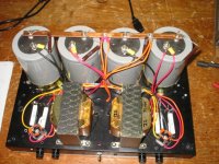
OK, I'm half done. I have a power supply ready for my upcoming JLH amp.
The two transformers have their primaries wired in series to give me half their normal secondary voltage. I'm getting about +/-24VDC. You can see the current sharing resistors, 0.47 ohms. Each transformer is centre-tapped and runs a separate bridge rectifier / capacitor pair (68000 uF per cap), although the rectified output is tied in parallel so neither side can hog too much current (which would unbalance the transformer primary voltages).
The transformers came from a pair of Advent powered loudspeakers I gutted.
I'll be using a capacitance multiplier as well; it will either fit on this chassis (two big heatsinks on the sides), or become part of the amp chassis.
Another couple or three years and I should have the actual amp built.
Attachments
Re: Rf oscillation at -ve peak
JLH suggests, for stability, that the first few cm's of o/p lead have some inductance and no capacitance. In other words they should be separate pieces of wire rather than held together in a sheath.
The conditions set up by this arrangement can, if everything else is OK, make the difference between stability and instability.
but on the original he does not use a Zobel so this could change significance of this idea. Still might be worth trying
mike
kambule said:thanks for your helps.
the leads to load is only 10cm long.
JLH suggests, for stability, that the first few cm's of o/p lead have some inductance and no capacitance. In other words they should be separate pieces of wire rather than held together in a sheath.
The conditions set up by this arrangement can, if everything else is OK, make the difference between stability and instability.
but on the original he does not use a Zobel so this could change significance of this idea. Still might be worth trying
mike
- Home
- Amplifiers
- Solid State
- JLH 10 Watt class A amplifier