Agree,lower THD and THD profile isn't same things.Very interesting. It's not 100 % certain 2.5 amps is better. The 1.1 A version has it's harmonics in a very nice order. OK the 2.5 amp version is better in an absolute sense, both better the JLH intended < 0.1% THD. The KEF LS50 speaker has 0.8% THD and the Quad ESL 63 0.1%.if not listening at maximum with full bass. Most speakers exceed 2%. Some say harmonics > 10 kHz don't count. Hard to say. When class AB I prefer not to see them.
Lower THD optimal bias isn't the same for different output transistors,especially when out. power is high, i will post what i have measure for 6w RMS using TTC5200 & MJ15024 soon.
As soon as THD isn't very high the more audible is the THD profile??????
Last edited:
I tried BC337-40 in LTspice, and at 14W there are distortions about 0.04% of 1kHz to 20kHz. Input transistor is 2SA992 and output 2SC5200, bias 1.75A, +/- 21V.
I only feared endurance as it was only 625mW
I found it OK when 8 ohms version. I had thought to add a small flag of baked bean can metal to the colector. When standing current it is fine. The question is would it change dynamically. My Indian 2N3055 were easilly above gain of 100 at 1.5 amps. There were T092 heatsinks in the old days. Obviously many thought this worthwhile. One can add a bit of metal to the PCB to help.
For CD input I guess 300 mV is about right. 20K volume pot perhaps.
different out different THD profile
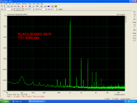
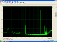
black board small signal trans a970 out trans ttc5200
BIAS=2.5A where THD is minimum
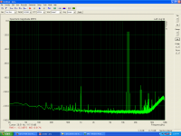
black board small signal trans a970 out trans ttc5200
BIAS=2.5A where THD is minimum
Attachments

Last edited:
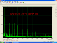
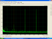
black board small signal trans.a992 out MJ15024
BIAS=1.7A where THD is minimum
BIAS=1.7A where THD is minimum
Attachments

Last edited:
thimios
interesting results, thanks for posting.
There will indeed be an optimum bias for the epibase 4MHz-type transistors. At higher currents the gain will reduce so the overall distortion will increase, but opposing that is the current swing which as a fraction of the quiescent current is smaller i.e. a more linear sweep.
Your results seem to support higher bias currents than people expected perhaps.
Nigel- I agree that distortion components over 10kHz should be avoided. In amplifiers showing poor THD there is a tendency to produce sum and difference intermodulation components. So a 10kHz signal and a 15kHz signal both producing "non audible" harmonics could generate a 5kHz intermodulation product if the thd is not low.
Very valuable measurements thimios, as you see the mj15024 has a stabilized Hfe at 1A by this it generates more odd harmonics than the increasing C5200 . Increase of Thd from 0.045 to 0.07 is mainly third harmonic .
thimios
interesting results, thanks for posting.
There will indeed be an optimum bias for the epibase 4MHz-type transistors. At higher currents the gain will reduce so the overall distortion will increase, but opposing that is the current swing which as a fraction of the quiescent current is smaller i.e. a more linear sweep.
Your results seem to support higher bias currents than people expected perhaps.
Nigel- I agree that distortion components over 10kHz should be avoided. In amplifiers showing poor THD there is a tendency to produce sum and difference intermodulation components. So a 10kHz signal and a 15kHz signal both producing "non audible" harmonics could generate a 5kHz intermodulation product if the thd is not low.
Well said. Could we do this testing with Thimios's help? Some say IMD is not important or overly stated. I notice Douglas Self keeps away from it whilst saying his designs are good on IM.
My brother was given a Goodmans Module 80 to improve. The sound was typical 1960's. It had all PNP outputs ( silicon devices, 2955's ). We suppose it was an old germanium design. Simon measured quite high IM distortion. The VAS was upgraded. Alas it oscillated so returned to factory devices. The VAS emitter had a silicon diode emitter to voltage rail. This was replaced with 56R to give the same DC points. The IM distortion was cured ( sorry I don't have the data ). I suspect in a technical sense we degraded the loop gain. The sounds was really nice due to doing this. My brother said the diode had slope resistance which was not ideal. The guy he did it for prefered it to various Naim amplifiers.
Evening gents, I have dragged this out of the cupboard to give me something to do indoors. The boards are built, I am assembling the case. However I forgot about the need to multiply AC supply voltage by 1.4 so my 35V ac transformer is giving me 48V DC off the rectifier. Is this going to be OK or is it a Star Trek "She cannae take it Cap'n" moment? If it's too much I can put the centre tap on the rectifier and get 24V DC at the rectifier, it will work but be low powered.
If no one said use the lower voltage.
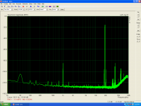
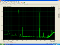


Is this what are you looking about?thimios
interesting results, thanks for posting.
There will indeed be an optimum bias for the epibase 4MHz-type transistors. At higher currents the gain will reduce so the overall distortion will increase, but opposing that is the current swing which as a fraction of the quiescent current is smaller i.e. a more linear sweep.
Your results seem to support higher bias currents than people expected perhaps.
Nigel- I agree that distortion components over 10kHz should be avoided. In amplifiers showing poor THD there is a tendency to produce sum and difference intermodulation components. So a 10kHz signal and a 15kHz signal both producing "non audible" harmonics could generate a 5kHz intermodulation product if the thd is not low.
Attachments
Very interesting and not too bad. Some say the JLH is not good on IMD without saying what good is. As usual measurments say far more. The ones who say this infer it's old school circuit has the same defects as early class AB designs. The dreaded TID comes to mind.
In a class AB deign it is usually the Miller capacitor which limits the feedback response to cause slew rate induced distortion. In the JLH, it is only the output transistors which have a slow response (unless high speed devices) and as mentioned with an fhfe of about 50kHz the JLH will work to 50kHz without TID. Or if at lower input levels than needed for full output, say half voltage (25% power) to 100kHz or more. Which is probably where most listeners operate the JLH as 1W is quite loud. Alternatively as long as the signal source does not have these high frequencies the JLH should be free of TID.The dreaded TID comes to mind.
That's a "side effect" of simple topology - also in simple 4-transistor cl. AB amps with CFP singleton input. IIRC G.Maynard had a essay on (I had to look it up on google right now) NFB "first cycle accuracy" which is inherent in a simple cfp singleton. (even if you make a small AB amp with a shitty germanium output pair) ...
The GEM
The GEM
TID is when we ignore the rules we usually set for simple desigs. For example when using potenial divider biasing of a single transistor we often use 1000% the current the base requires. This ensures we have plenty of curent and the biasing is very reliable. Many amplifiers use transconductance where the previous stage is forced to supply the exact current required. That's fine if it can. Add to that a jump in the output stage when class AB so as to have much trouble. Class A reduces the problem to the transconductance alone ( I think ). Other problems are often designer choices. It would be interesting to speculate about PNP input transistor current. The means making the feedback resistors 1/2 the value and the capacitor double the size if doubling the current. It would be interesting to keep the 8K2 the same at first. If double the current is worthwhile I can not say. It should make the older transistor types like BD139 work harder. Not bad for a SIM test I feel.
That's a "side effect" of simple topology - also in simple 4-transistor cl. AB amps with CFP singleton input. IIRC G.Maynard had a essay on (I had to look it up on google right now) NFB "first cycle accuracy" which is inherent in a simple cfp singleton. (even if you make a small AB amp with a shitty germanium output pair) ...
The GEM
The 25 watt Gem looks interesting. I like the capacitor to the input long tail pair feedback side. Not the use. More the placement.
I posted a very simple 5 watt A 20 watt AB MOS FET design typically using Exicon 10N/P20 FET's/ I returned 50 kHz junk to the VAS to get similar results as when using very fast complimentary feedback pairs ( BD140/139 2SC5200 2SA1943 ). My reasoning here is very loud music never is higher than 5 watts. However a headroom of 100 watts sounds as if the amplifier has lower distortion. The train whistle on the Decca Stereo test record is heard in the station roof if the transient power is there ( later light blue transistor cut shows this best, it's also cheaper to buy as the dark blue lable is for the collectors ) The rounding off of class A amplifiers can be transient rather than that we can hear > 35 kHz. Whilst 20 watts is not 100 watts it is usefully greater. The FET's will limit the ultimate current. All the same 35 watts 4 ohms was possible ( I think ). My VAS feeedback was so as to throw a very large number of parts away without throwing the performance away. The amplifier had no measurable problems to 100 kHz. It sounded bright and very like a OPA604 driving feedback pairs.
Douglas Self has a Class A + Class C design ( Hitachi Dynaharmony clone ) . Replacing his class A with MOS FET's as the Hitachi/Exicon type might be interesting. 5 watts should be enough unlike his 20 watts.
Last edited:
If you want a 4 or 5-watter for 8 Ohm, you can do it easily on 18V with BC560/BC637-16/TIP3055. You can go lower voltage for 4 Ohm (at 15V), but you need higher hfe transistors like f.e D44H11 or 2SD553 (the better hfe on top not bottom!) Needs "custom compensation" of course...
Thanks Nigel, I'll use the lower voltage to get it going and think about a different tarnsformer later if I need to.If no one said use the lower voltage.
- Home
- Amplifiers
- Solid State
- JLH 10 Watt class A amplifier