Andrew,
Should it not be 0,14 mV for 86 dB, rel 2,83 V now and 0,045 mV for 96 dB ?
It would be great if someone has done similiar measurements.
There are lots of JLH-amp. information here, but difficult to find measurements.
Should it not be 0,14 mV for 86 dB, rel 2,83 V now and 0,045 mV for 96 dB ?
It would be great if someone has done similiar measurements.
There are lots of JLH-amp. information here, but difficult to find measurements.
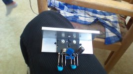
Here are my measurements of the JLH 2005 amplifier.
Power from a CAPMultiplier, with +-21 V DC and 1,04 A.
It would be great to see other measurements here from this amplifier.
(I built this power amplifier also about 1971. From the article in Wireless World.
The original circuit without current sources. )
/Christer
Power from a CAPMultiplier, with +-21 V DC and 1,04 A.
It would be great to see other measurements here from this amplifier.
(I built this power amplifier also about 1971. From the article in Wireless World.
The original circuit without current sources. )
/Christer
Attachments
The clipping pic is way too high to be described as just starting to clip.
You need to back off the input until clipping is just not quite visible.
Then measure your Vout, that is visibly clip free.
Alternatively look at the THD take off as clipping is approached and set yourself a THD threshold to measure the Vout. Most use THD+noise @ 0.1% as the maximum power available before clipping.
High distortion amplifiers cannot use that 0.1%, because they are hovering just below 0.1% much of the time. They may need to use 0.5%, or even 1%, if the THD is really high.
You could set your clip free maximum THD+noise at 0.1% and you see ~4.8W as the maximum power output.Yes I did this earlier and plotted the result in Excel.
Looks like this.
Freq=1kHz.
Setting to 0.5% and you get ~11.4W
At 0.5% THD+noise the signal will not be visibly free from clipping. The distortion is quite gross.
Maybe a sensible THD for extracting a useful maximum power output would be 0.2%. or 0.25%.
And whenever you quote maximum power, that THD set point has to be stated as part of the specification.
Yes of course. The max output power must be stated with THD+N figures, output load, both channels driven….
When I use a lab power supply for the amplifier it’s easy to change the Power supply voltage and also to adjust Iq of the amplifier a bit, and see what happens. From the Lab power supply I can also read the total current drawn.
Right now when the load is 8Ohm, it is Iq that limits the power output. A loudspeaker is not a pure 8 Ohm load as you know. So I will continue to play around a bit more here.
I also need to mount the output transistors on bigger and final heatsinks.
/Christer
JLH 2005 with MJ802
I found some MJ802 output transistors so I had to test them in my JLH 2005 power amplifier as well.
A bit unexpected that I had to replace a resistor in the current source from 10 to 68 Ohm in order to have the same IQ of 1,0 A. The MJ802 had much higher hFE than my ordinary MJ15003.
This could be good to know if you can´t trim IQ down to 1A.
Measurements and drawing attached.
/Christer
Attachments
I found this on youtube : Publicat pe 30 aug. 2014
2x32/8ohm, 2003 version with 4xMJ15003/channel, very strong and very hot
However i cannot find anything about 2003 or 2005 versions using google, just the 1996 which is 2x15w/8ohm.
I looked around Geoff Moss's site but i can see you guys have brought further improvement.
Would be glad to find out the exact modifications made in order to obtain more than 15w and any other SQ improvements that have been made since the 2004 update on that website.
Roland.
Hi Roland,
For myself I found here on the Vendor forum free PCBs :
Siliconray Online Electronics Store - diyAudio
It uses +- Power Supply, Current Source and it is about the same design as the Geoff Moss version. I think its a good idea for you to use the George Moss version with 4*MJ15003 !
Look for PCBs on ebay also.
/Christer
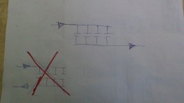
To remember one of the finest circuits:
(but this is more a clh than a jlh,-)
Great amps!
I suggest to build the origin: One (+) psu for all, not the Two (+ and -) psu-version. To get out the signal use 4 x 470 uF or so. Connected as shown (coupling caps in general). NOT 4,7 mF and 10 uF or so. Everytime the same values, same types.
My suggests,-!
Attachments
With class A and in fact any applications where significant heat is dissipated, you find that placing the output stage devices close together is a bad idea. If you want to dissipate heat efficiently and avoid a hot spot on the heatsink with unnecessary derating, as wide a spacing as possible between the transistors, is essential..... Connected as shown......
If you want to dissipate heat efficiently and avoid a hot spot on the heatsink with
unnecessary derating, as wide a spacing as possible between the transistors, is essential.
Yes, in fact the thermal resistance spec of a large heat sink is ONLY valid for uniform dissipation
across its entire mounting surface.
I would aim for transitors to be mounted side by side rather than one above the other, if at all possible.... saves baking the top transistor with the heat from the bottom one!
Also somewhat surprisingly black heatsink will dissipate heat MUCH MORE efficiently than silver.
Also somewhat surprisingly black heatsink will dissipate heat MUCH MORE efficiently than silver.
Last edited:
If heat sink is very deep (say copper block with heat pipes, fins and a fan) close mounting is not an issue if sink doesn't even get warm. Same with water cooling block. Inside computers and laptops, tight spacing is the norm. I may try forced convection CPU coolers on the OPS of my next class A project. Much less expensive than massive aluminum heat sink.
black heatsink will dissipate heat MUCH MORE efficiently than silver.
Thermal radiation is in the infrared, and the black color has better emissivity.

So where you at with it Tom ?
I had a Spice file of the JLH (one I made earlier as you do🙂) so I just tried your supply (no problem) but was rather surprised that the transistor types (models) made such a difference to the AC gain.
The files are here if anyone wants a play.
Tom... if you are still having problems then measure and record the voltages at each transistor for E,C and B and post the results. Also check by measurement that all the resistors are what they are supposed to be.
As Nico says, the JLH works pretty much out of the bag so something basic is amiss somewhere.
Hello JLH v1 great. How is thw sound Mooly ?
- Home
- Amplifiers
- Solid State
- JLH 10 Watt class A amplifier