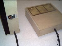
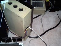
The reason I had to use blow torch was that I did not know thick copper bus bars do not go well with snap in type capacitors. I learn it the hard way. I already bought, cut, drill and tinned all eight copper bars before I realised my 35W, 40W and 80W solder irons did absolutely nothing except cold solder joint for sure. Being stubborn I went and bought the blow torch, heat up the copper bars, pre load the holes with solder and place it on the caps pins, but with five caps in a row, when one pin goes in the other ones already cool and harden and prevent it to line up all 5 pins with 5 holes the same time. Like I posted in another thread before, I skinned the caps amoung other things, not on purpose to try different sonic results 🙂
And waving a blow torch flame inside the PSU box had a lot of accident because you can not really see the true end of the flame!
Never use thick copper bar unless the caps are srew-in types!!(For Newbies like me)
Chris
The Butcher
And waving a blow torch flame inside the PSU box had a lot of accident because you can not really see the true end of the flame!
Never use thick copper bar unless the caps are srew-in types!!(For Newbies like me)
Chris
The Butcher
 ...
... 
Soft start
And I have forgotten to thank Rod Elliot's excellent site that I have build the soft start circuit based on his site. It works great with my psu.
Thank you Rod,
Chris
And I have forgotten to thank Rod Elliot's excellent site that I have build the soft start circuit based on his site. It works great with my psu.
Thank you Rod,
Chris
Only add one cap to the existing amp
I was given a old new pair of 4.7uf MKP 250V AC 400V DC caps build for audio, brand name unknown. My brother in-law bought it around 1990 but never used them. I just solder it to the existing bunch of 5 100nf caps.
So now my C1 has 5@ 100n and 1@ 4.7uf. Wow what a big improvement. This is good. I am very happy. The advantage of the updated high power version has over the JLH for ESL that I can see tonight is the DC offset and Iq is very easy to set and very stable. I do not feel the need to set the Iq to 4A. The switch on from stone cold, voltage across R9 141mV and DC offset at speaker binding post 70mV. After 15 to 20 minutes both became stablised with voltage across R9 150mV, DC offset at 1mV
Plan to listen to this for a week then remove 5@100n to see..
Sound very nice those MJ21194 with the ccs updated version, you should give it a try...
Chris
Better..
I am tweaking the updated version of JLH. I am pushing it closer for sure or better (for certain CDs) to my previous JLH for ESL. One thing I have tried this morning work quite well for my amp.
I am keeping the feedback cap C4 with 470uf, and this one is a very cheap off the shelf cap G.LUXON 470uf 35V cost $1.40cdn for a pack of two. I put in a 0.1uf polypropylene cap from Digi-key part no P3104-ND to bypass C4. This little Japanese bypass cap can do wonder to the sound. The vocal just solidify in front of your forehead. The focus of imaging is much more precise.
The reason why I tried this was because I used one of this little cap last night to bypass my cheapie C1 to improve the too soft bass. It worked really well, so I looked into the circuit to see where else can I try with this bypass cap. If the result is no good I can always remove it quickly since I can run my amp open chassis and work on it any time.
So to sum up, if you are using cheap parts like I do and if you feel your amp has soft bass. Try to find the best top end sound of C1 first, then put in that little bypass cap with C1 to improve the bass.
If you feel that the soundstage is too flat and not interesting and hard to lock into a position in mid air for the sound of a particular instrument then try bypass C4 with this little Japanese cap.
Hope this can help those using generic parts like me.. 😉
Chris
Hi!
I would like ask:
What is the minimum Transformer VA rating for the JLH 96 updated version (15W) with unregulated PSU?
200-300VA for 2 channel?
Thanks!
I would like ask:
What is the minimum Transformer VA rating for the JLH 96 updated version (15W) with unregulated PSU?
200-300VA for 2 channel?
Thanks!
Check my print, please
Hello
i have drawing a PCB for my JLH 96 updated version. but im new to this, so ill like to have someone to take a lock at it first.
will i get a problem whit grond noise.

Hello
i have drawing a PCB for my JLH 96 updated version. but im new to this, so ill like to have someone to take a lock at it first.
will i get a problem whit grond noise.

PCB layout
He Calebay,
Obviously something went wrong when you tried to upload your file. Anyway, I have completed my layout for this amp. Look at one of my previous posts for the schematic I used. The PCB are already made and they will be tested in the next couple of weeks. I will post the results when I've got them.
For now, here is the layout I made.
Ps1: I haven't really checked the correct pins for the transistors. So I will post a rev 1.1
Ps2: Have a look at the Hiraga articles for grounding and layout tips.
Ps3: If you would like to upload an image, you will to use the browse button at the bottom of the screen to select and upload your picture to the remote server.
If anyone has any comments about my design, which I can incorporate in rev 1.2 design, feel free to post them.
Attachments
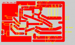
The traces on your PCB look are very tight together, especially the ones at C6. You may want to have more space between them.
What did you use to lay out the PCB?
What did you use to lay out the PCB?
They traces appear to be very close to each other indeed. The PCB I made is actually 10% bigger, so it doesn't seem to be a big problem. I will make the distance bigger for a next version, thanx for the point.
I used circuitmaker and traxmaker for the design. Because of my lack of experience, I like to simulate every circuit that looks interesting. Circuitmaker has proven to be a very easy and clear program to do the job for me.
I used circuitmaker and traxmaker for the design. Because of my lack of experience, I like to simulate every circuit that looks interesting. Circuitmaker has proven to be a very easy and clear program to do the job for me.
Would you be willing to share your artwork? Well, I know you already have, but a version without the silkscreen that I could use directly for making my own PCB? I have all the parts for this amp but haven't built it yet. I was going to do it on Veroboard, but a PCB would be nice.
Paulb,
You can find the Traxmaker files here.
Note: This is not a tested PCB and I am not a experienced PCB designer (actually this is my first ever ); ) so use this at your own risk.
I would be interested in any changes that are made on these PCB, so feel free to email the traxmaker files to me.
The PCB will be tested soon and I will post the results, so you may want to wait for that.
- Home
- Amplifiers
- Solid State
- JLH 10 Watt class A amplifier