Re: maths continued
Well, a lot depends on how you analyse the Q1/Q2/Q3 output stage, which can be looked at in several different ways, ie Q3 acts as an accurate current phase splitter, Q2 is a voltage follower with Q1 as a variable current source emitter load or Q1 is a common collector stage with Q2 acting as a variable current current source collector load.
Whichever way you look at it, there is a degree of effective 'push-pull' action which results in a higher maximum output current, for a given quiescent current, than would be the case for a single-ended output stage. With perfect transistors, the maximum output current could theoretically be twice the quiescent current but unfortunately we do not have any perfect transistors available.
Many simulations using a variety of power transistor models indicated that in the real world the peak output current could be between about 1.2 and 1.5 times the quiescent current, with the majority of models giving a figure between 1.3 and 1.4, so I chose 1.35 as a suitable multiplier to use for design purposes.
At the same time as I was carrying out these simulations, Rod Elliott was developing his DoZ design (a similar output stage to the JLH) and he determined empirically that the optimum quiescent current was about 0.75 times the required peak output current so our conclusions (mine from simulation and Rod's from measurement) were in agreement.
deduikertjes said:What puzzles me is the statement
Is that easy to explain?
Well, a lot depends on how you analyse the Q1/Q2/Q3 output stage, which can be looked at in several different ways, ie Q3 acts as an accurate current phase splitter, Q2 is a voltage follower with Q1 as a variable current source emitter load or Q1 is a common collector stage with Q2 acting as a variable current current source collector load.
Whichever way you look at it, there is a degree of effective 'push-pull' action which results in a higher maximum output current, for a given quiescent current, than would be the case for a single-ended output stage. With perfect transistors, the maximum output current could theoretically be twice the quiescent current but unfortunately we do not have any perfect transistors available.
Many simulations using a variety of power transistor models indicated that in the real world the peak output current could be between about 1.2 and 1.5 times the quiescent current, with the majority of models giving a figure between 1.3 and 1.4, so I chose 1.35 as a suitable multiplier to use for design purposes.
At the same time as I was carrying out these simulations, Rod Elliott was developing his DoZ design (a similar output stage to the JLH) and he determined empirically that the optimum quiescent current was about 0.75 times the required peak output current so our conclusions (mine from simulation and Rod's from measurement) were in agreement.
EUVL said:Geoff,
It is my (limited) experience that a factor of 3 in terms of toroidal VA will help to minimise of tranformer humm.
But this is also dependent on the size of the capacitor immediately after the rectifiers, and of course the transformer design itself. The maximum ripple current can be easily 10 times of Iq with a 10% duty cycle.
IMHO, the price and size difference between a 500VA and a 800VA is really minimal, compared to the rest (heatsinks, housing, and what not).
Patrick
Patrick
I don't disagree with your comments. A higher factor can be beneficial if one has the physical space and can tolerate the extra expense. However, it can sometimes be difficult to get a higher VA rated transformer with secondary voltages low enough to suit the JLH, ie 18 to 25Vrms depending on the minimum load impedance, the type of power supply used (regulator, cap mult or simple rectifier/capacitor) and the required power output.
If it were me, I would use separate power supplies for each channel and, for Marco's rail voltage and quiescent current, a 300VA transformer for each one. Generally this also avoids the need for a soft start circuit, at least for those with the benefit of a 230V mains supply.
Geoff
Geoff,
All valid points, especially regarding low voltage high current.
Those, like me, who build bridged Class A amps would know.
Cheers,
Patrick
All valid points, especially regarding low voltage high current.
Those, like me, who build bridged Class A amps would know.
Cheers,
Patrick
Hi Chris.
It's sad to hear that you have lost a speaker.I believe it has
happened to most of us here.My amplifiers have fried quite a few
small test speakers.
Maybe it is not applicable to you, but for the first timers
contemplating building a JLH class A amp, I would suggest
building the 69 version.The output capacitor would surely
save the speakers.
I have not built the direct coupled version yet.If you apply two
feedback paths to the 69 version,one before the capacitor and
one after it,I find the sound of this amplifier most pleasing.
Perhaps this is a very subjective point, depending on what
kind of music you like, how loud you like etc.
If anyone has done comparisons between the direct coupled
version and the 69 version, I would like to hear your views.
Cheers
Selim
Selim,
On Geoff's site you will find jlhrvs.htm which contains a report on using output caps or not.
Very interesting reading although it still puzzles me how the author used ouput coupling caps on its dual supply JLH without destroying the caps by a lac of forward bias.
greetz, MArco
By the way: I finished Rod Elliots loudspeaker protection. So last night I was listening to my JLH's with some more Iq (0,5 A). Sounded NICE!
(although I have hum in the right channel which (I think) is due to a not properly functioning cap multiplier. I measure 0.1 AC ripple on the supply lines)
Geoff
I agree with your comment that the JLH would normally provide only about 1.35 times quiescent. This was the case using original transistors of the 2N3055 type.
If you use linear gain transistors like the MLJ3281A then I believe it is possible to do much better- perhaps almost 2.
cheers
John
I agree with your comment that the JLH would normally provide only about 1.35 times quiescent. This was the case using original transistors of the 2N3055 type.
If you use linear gain transistors like the MLJ3281A then I believe it is possible to do much better- perhaps almost 2.
cheers
John
john_ellis said:If you use linear gain transistors like the MLJ3281A then I believe it is possible to do much better- perhaps almost 2.
Hi John
If your comment is based on simulation, using OnSemi's model of the MJL3281A, then I would have to disagree as this model is seriously flawed. However, if your result is based on actual measurement then I would like to hear more. Unfortunately, using the MJL3281A requires additional components to ensure stability which will lower the open loop bandwidth to significantly below 20kHz. I believe that one of the reasons why the JLH sounds as good as it does is that the open loop bandwidth extends virtually across the full audio range.
Geoff
Hi Geoff
Have a "JLH original" with MJL3281A's on the bench. Will measure and let you know!
BTW it works well with wide bandwidth...
I'll post the circuit as well if u like.
cheers
John
Have a "JLH original" with MJL3281A's on the bench. Will measure and let you know!
BTW it works well with wide bandwidth...
I'll post the circuit as well if u like.
cheers
John
Hi Geoff
Measurements on a Class A amp.
I started by measuring the gain linearity of the MJL3281A's I'd wired into my bench JLH-10W circuit.
Within the very rough accuracy of the resistors, to 2 sig. figs, the gain varied from 90 to 96 to 94 over the range 80 mA to 4A. THis is similar to the published typical gain (100 flat from 5 mA to 5A).
In JLH's original Class A amplifier, the upper and lower output transistors share the driver transistor current. So when one transistor conducts more, it has to take base current from the other. If the gain linearity of the transistors is poor, the increase in one is not linear with the decrease in gain in the other.
Old transistors like the 2N3055(later called H) from RCA may have had a gain of about 50 at 1 A and 30 at 3A. The base current of the two devices might have been sitting at 20 mA, but when one transistor just reaches the point of switching off, a maximum current of 40 mA is available for the device turning on. If it's gain has dropped to 40, then it can only conduct 1.6A, so this explains the early ratios which were around 1.35 in practice as you mentioned.
BUt if the current gain in the output transistors is linear, then the current should in principle be able to double, since 2X Ib gives 2x Ic for the same gain.
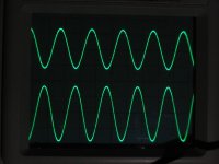
I then measured the current in the output stage. The oscilloscope photo attached shows the output at the point of clipping (only ~ +/- 12V peak into 7.5 ohm load) while the lower trace shows the current which reaches a peak of 1.8 x idling, which coincides with the dotted reference line.
OK that's not quite 2 but it's better than 1.35.
cheers
John
Measurements on a Class A amp.
I started by measuring the gain linearity of the MJL3281A's I'd wired into my bench JLH-10W circuit.
Within the very rough accuracy of the resistors, to 2 sig. figs, the gain varied from 90 to 96 to 94 over the range 80 mA to 4A. THis is similar to the published typical gain (100 flat from 5 mA to 5A).
In JLH's original Class A amplifier, the upper and lower output transistors share the driver transistor current. So when one transistor conducts more, it has to take base current from the other. If the gain linearity of the transistors is poor, the increase in one is not linear with the decrease in gain in the other.
Old transistors like the 2N3055(later called H) from RCA may have had a gain of about 50 at 1 A and 30 at 3A. The base current of the two devices might have been sitting at 20 mA, but when one transistor just reaches the point of switching off, a maximum current of 40 mA is available for the device turning on. If it's gain has dropped to 40, then it can only conduct 1.6A, so this explains the early ratios which were around 1.35 in practice as you mentioned.
BUt if the current gain in the output transistors is linear, then the current should in principle be able to double, since 2X Ib gives 2x Ic for the same gain.
I then measured the current in the output stage. The oscilloscope photo attached shows the output at the point of clipping (only ~ +/- 12V peak into 7.5 ohm load) while the lower trace shows the current which reaches a peak of 1.8 x idling, which coincides with the dotted reference line.
OK that's not quite 2 but it's better than 1.35.
cheers
John
Attachments
John
Thanks for the info. I am always pleased to read/hear feedback about the JLH Class-A. Your measurements confirm that which I had determined from simulation.
Did you need to add anything to the circuit to ensure stability? From comments received previously, it would appear that the original 1969 circuit is more stable with higher ft output transistors than the later 1996 revision, possibly due to the bootstrap Iq arrangement rolling off the gain at higher frequencies. For the former, at lot probably depends on the physical layout and associated parasitics.
From feedback I have received, the 1996 circuit is always unstable, without additional compensation components, when more modern, higher ft output transistors are used but the original version is more tolerant and sometimes works, sometimes doesn't.
Geoff
Geoff
I added a small capacitor to ensure stability. The bandwidth with this capacitor is still about 1 MHz.
The input filter could probably work with a much smaller capacitor (47 pF also?)
SImulations indicate that as the circuit stands, operation up to 200 kHz does not overload the input stage, but higher frequencies might.
A larger feedback capacitor is needed to ensure that the input stage does not overload, but I suspect that 200kHz margin is adequate for most signal sources?
cheers
John
Attachments
current limited
Can anybody tell me what actually happens when the JLH amp runs out of current (Iq) when driven to loud in low impedances.
I do understand that the amp clips when the voltage needed to drive the speaker to a certain power is larger than the rail voltage.
But what happens with the waveform when the amp is running out of current?
thanks, MArco
Hi Marco
I've raised this point before, in other threads, but many threads seem to like going round in circles...
if your JLH69 overloads by clipping, nothing much happens except that the waveforms internally on the second stage transistor (phase splitter) saturate.
if your JLH69 overloads in current because of a low load impedance, then you might be in trouble. I've mentioned that the phase splitter could cause the upper output transistor base to reverse bias by as much as half the supply voltage. In this case the waveform is a square wave (for a sinewave input) with the upper output potentially becoming a liability.
This isn't too clever, and it may have caused one contributor's trannys to expire, since most bipolars will "blow a fuse" if their bases are more than about 7V backwards.
To stop this risk, either make sure that your speakers won't short or are 8 ohms or so, or put a fast diode in series with the upper output base!.
cheers
John
Dear John,
Thanks for your answer. I'd like to read up a bit more on this, so I've looked in your earlier posts in other threads and couldn't really find. Can you please point me out some relevant posts?
thanx, MArco
Thanks for your answer. I'd like to read up a bit more on this, so I've looked in your earlier posts in other threads and couldn't really find. Can you please point me out some relevant posts?
thanx, MArco
I have built JLH higher power version.
When i first time power on amp. sounded magic, but when i put
pcb, psu, ...into chassis , amplifier do not sound so good, and now I can hear litlle hum.
Where is the problem to worst sound and hum?
Soory my English is not good
When i first time power on amp. sounded magic, but when i put
pcb, psu, ...into chassis , amplifier do not sound so good, and now I can hear litlle hum.
Where is the problem to worst sound and hum?
Soory my English is not good
Welcome to the forum dary. I see this is your first post. I hope you enjoy yourself here. A good place for you to look at is the website run by Geoff Moss. He is the "Geoff" who you see posting on this thead. Try this site www.tcaas.btinternet.co.uk and look for his article on "earthing". It is in the section marked, "The JLH Class- A amplifier". Click on that and you will get a lot of information on building the amp'. I think that will be the best place to start.
If I understand there maybe problem about earthing
I will try to change earthig points
I had forgoten how important is earthing...
Thanks for your attention
My JLH:
- dual PSU
- 2 X 400VA toroid, 27V secondar
- 80000 mf capacitor per channel
- shunt regulator TL431
- KBPC 5004 rectifier
- 2sa970, 2sc3421, 2sa1358,
- high gain selected MJ15003
- huge heatsink
Sound is natural , smooth , liquid and surprisly powerful
Amplifier work stable, without feedback capacitor
Only problem a litle oscilation at higher voltage supply (2SA970)
at lover voltage supply there is no worth about oscilation
As I sad there is a litlle hum (earthing) problem
I realy enyoi when listening this amplifier, (just I would like to hear a little much higher frequencies)
Hello, with rgards the earlier posts in this thread concerning the NAD 302 amp and modding/sound quality I have just replaced all caps with Elna cerafine and a few Black Gates including two N-type ones. The power caps are now 10000uf 63v compared to 6800 50v. The sound is absolutely brilliant. I shall, funds permitting purchase some Shinkho resistors and throw them in at some point together with a quality pot (TKD ko-on) and see what that does. If the design sounds good with cheap components then it must be a good starting point for upgrading surely?
Can anybody tell me what actually happens when the JLH amp runs out of current (Iq) when driven to loud in low impedances.
Marco, with bipolar transistors and thus a low internal resistance JLH was capable of some larger current to (impedance) critical speakers. I have now fets as last output devices in my hybrid amp, but mis sometimes the bass drive JLH can deliver.
Here they are, my JHL monoblocks. But they keep cool now in the attic:
http://img213.imageshack.us/my.php?image=jlhamp9by.jpg
Should mod them too with cerafine/black gates.
Hello I´m a new member here and I have longed to build the JLH amp a long tme now,but i have not found any "readymadepcb´s" yet like that the user PaulB has,can anyone "PaulB" mail me the gerberfiles of it,because i can´t because my account are under moderation. 🙂
- Home
- Amplifiers
- Solid State
- JLH 10 Watt class A amplifier