Hi Chris ma
I suppose it isn't really a VAS as it works as a voltage-and current stage (VACS)? but yes, that's the transistor to check.
cheers
JOhn
I suppose it isn't really a VAS as it works as a voltage-and current stage (VACS)? but yes, that's the transistor to check.
cheers
JOhn
Second Breakdown
The BD139 checked out ok, but I have to put a new one in now. Very difficult to work on this one in a tight spot.
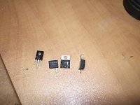
These 2 Ohmite 0R1 resistors R13, R15 in their damaged state see pic.
Three out of four Mj21194 output transistors were damaged. The Q2, Q2A, Q1 were damaged, Q1A is the only one survived.
I gathered it was because through the years of usage I didn't maintain it by go around and re-secure all mounting screws of the output transistors. The stress of the heat had lossen up the screws and slowly the contact for heat transfer was diminished that lead to this failure.
The BD139 checked out ok, but I have to put a new one in now. Very difficult to work on this one in a tight spot.
These 2 Ohmite 0R1 resistors R13, R15 in their damaged state see pic.
Three out of four Mj21194 output transistors were damaged. The Q2, Q2A, Q1 were damaged, Q1A is the only one survived.
I gathered it was because through the years of usage I didn't maintain it by go around and re-secure all mounting screws of the output transistors. The stress of the heat had lossen up the screws and slowly the contact for heat transfer was diminished that lead to this failure.
Attachments
Fixing it
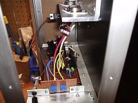
For the time being I have replaced the damaged parts with what I have in hand just to try things out.
2 MJ21194 and 1 2N3005
1 Ohmite 0R1 25W thick film power resistor as R13
1 NTE 0R1 2W carbon power resistor as R14
1 BD139 as Q3
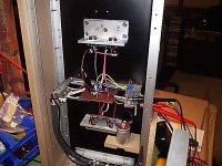
using the variac and bring up the voltage checking the Iq current and DC offset. This pic is taken 2 minutes after switch on with full power. This time I am aiming to set the Iq at 138MV across R13.
For the time being I have replaced the damaged parts with what I have in hand just to try things out.
2 MJ21194 and 1 2N3005
1 Ohmite 0R1 25W thick film power resistor as R13
1 NTE 0R1 2W carbon power resistor as R14
1 BD139 as Q3
using the variac and bring up the voltage checking the Iq current and DC offset. This pic is taken 2 minutes after switch on with full power. This time I am aiming to set the Iq at 138MV across R13.
Attachments
This 2 CCS version is so easy to adjust the DC offset and Iq current. The power on from cold to after an hour effect on Q3 has very steady effect on DC offset and the Iq current has changed from 136MV to 139MV from stone cold in an hour. I am very please with that.
Attachments
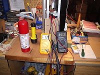
mikelm said:I glad u keep the fire extinguisher handy ... 😀
Always with fear and respect when working and in our case playing with fire literally

chris ma said:Have to wait another hour before I connect it back to the system to see if the speakers were damaged. I hope they are ok🙁
The Jordan Jx53 voice coil fried....
Really sorry to hear about your amp and speaker, Chris. Do you think it was overheating, then? I'm seriously thinking about adding an overtemperature shutdown to my amp. I don't think there's any way to guarantee saving the speakers if a transistor shorts.
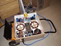
For those of you who weren't following Chris's progress back a few years ago, here's a good shot of what his amp looked like:
http://www.diyaudio.com/forums/attachment.php?postid=92766&stamp=1039327729
Weren't there casters on it too, or was that somebody else's?
For those of you who weren't following Chris's progress back a few years ago, here's a good shot of what his amp looked like:
http://www.diyaudio.com/forums/attachment.php?postid=92766&stamp=1039327729
Weren't there casters on it too, or was that somebody else's?
a fuse on the o/p made from a different grade of resistance wire is a quick and easy solution with very little impact on the sonics
Thanks guys
Thanks Paul,
The picture of that amp in your link is still working fine today. That is the pair of Geoff's original version of JLH for ESL using Mj15003 to power the pair of Jx150 and they have Vellemen K4700 speaker protection kits installed and regulate PSU. I have not make any changes to those.
The one that fried last weekend is the newer 2 CCS and using big CLC remote power supply using Mj21194 output transistors.
In my system I am using active 3 way, for each channel I am using the following
1 JLH using Mj21194 to power the Jx53 and a ribbon tweeter
1 JLH using Mj15003 to power the Jx150
2 BrianGT GC to power 2 X 12 inche H frame subwoofers
This time the Mj21194 burned out due to second breakdown means overheat over a prolonged period shorten the life span of these transistors. Luckyly the ribbon has a transformer to survive this ordeal but the Jx53 is not that lucky.
Mike,
I have to try and find one Jx53 only for now otherwise I have to find a new speaker project suitable for OB three way. Now it is very difficult to go back to boxes since I have acquired the taste of open baffle. Can you please explain further with your prevention scheme.
paulb said:Really sorry to hear about your amp and speaker, Chris. Do you think it was overheating, then? I'm seriously thinking about adding an overtemperature shutdown to my amp. I don't think there's any way to guarantee saving the speakers if a transistor shorts.
For those of you who weren't following Chris's progress back a few years ago, here's a good shot of what his amp looked like:
http://www.diyaudio.com/forums/attachment.php?postid=92766&stamp=1039327729
Weren't there casters on it too, or was that somebody else's?
Thanks Paul,
The picture of that amp in your link is still working fine today. That is the pair of Geoff's original version of JLH for ESL using Mj15003 to power the pair of Jx150 and they have Vellemen K4700 speaker protection kits installed and regulate PSU. I have not make any changes to those.
The one that fried last weekend is the newer 2 CCS and using big CLC remote power supply using Mj21194 output transistors.
In my system I am using active 3 way, for each channel I am using the following
1 JLH using Mj21194 to power the Jx53 and a ribbon tweeter
1 JLH using Mj15003 to power the Jx150
2 BrianGT GC to power 2 X 12 inche H frame subwoofers
This time the Mj21194 burned out due to second breakdown means overheat over a prolonged period shorten the life span of these transistors. Luckyly the ribbon has a transformer to survive this ordeal but the Jx53 is not that lucky.
Mike,
I have to try and find one Jx53 only for now otherwise I have to find a new speaker project suitable for OB three way. Now it is very difficult to go back to boxes since I have acquired the taste of open baffle. Can you please explain further with your prevention scheme.
Hi Chris ma
sorry to hear of more troubles.
Not sure definitely whether your problem was loose transistors. Screw fittings don't usually work loose unless they're vibrating, but maybe silicone washers "unstretched"?
I wonder if you have oscillation causing the VAS transistor to reverse bias the upper output transistor....
it would suffer proportionally inreasing damage depending on the volume level in the amp.
But an overtemperature limit would still be worht it I think!
cheers
John
Really sory to read about those dead speakers. Thats why I still don't dare to go for it with my newly constructed JLH's (the are still running on Ig = 150 mA).
I'm now contructing the Rod elliot speaker protection circuit. That will give me some pease of mind...
Anyone has any experience on this one? Glad to hear some comments.
greetings, MArco
I'm now contructing the Rod elliot speaker protection circuit. That will give me some pease of mind...
Anyone has any experience on this one? Glad to hear some comments.
greetings, MArco
Maths ...
Now that both my channels are playing (Iq of 0.15 A) it's about time to get into the maths (or should I have done that before hand ;-)). Please help me with appropriate comments.
As I've acquired some really massive heatsinks there is no need to take these into account. The thermal resistance from transistor to sink will be the limiting factor thermal wise.
Now we've that out of the way let's comtinue...
The rails are 24 Volts (plus and minus that is); lets asume 3 V losses (as per Rod Elliots article). I expect the impedance of my speakers to stay above 5.5 Ohms. The Iq to take full advantage of the voltage swing to produce max power in 5.5 0hms then has to be: U = V/R = 21/ 5.5 = 3.8 = Iq min. The delivered power into 5.5 ohms will then be: P= UV = 3.8 * 21 = 80 Watts. This is incorrect as the ouput power should be RMS and this is calculated peak to peak. Should it then be P = 3.8 * SQRT(21) = 17 Watts ? or P = 3.8 * 2 * SQRT(21) = 35 W? My guestimate will be the second option. Is that correct?
With no music playing there is no other place for the current to go than into heat in the heat sinks. So the heat to dissipate will be 24 * 3.8 = 91 W. This will be shared over the number of output resistors. So with two that will be 45W dissipation of heat per transistor. In the high power version with 4 transistors that will be 23 W per transistor.
According to this reasoning the heat dissipation has to decrease when playing music. The energy used to drive the speaker is no longer avaiable to heath up the heat sink. Of course it is not wise to rely on this to downsize the neaded heat sinks.
Lets recalculate for 4 and 8 ohms load to compare to other amps:
4 Ohms: 4 Ohms ask for a higher current. As we have an Iq of 3.8 no more current will be delivered. So the max power into 4 Ohms will be either 17W or 35W.
To be able to drive 4 ohms speakers to max power we should have an Iq = 21/ 4 = 5.25 A. Total heath dissipation will be 126 W. High power version needed to share this over 4 transistors to give 31 W per transistor.
8 Ohms: U= V/R = 21/ 8 = 2.6 Amps asked for at max power. The Iq of 3.8 allows for this. P = 2.6 * 2 * SQRT(21) = 24 W.
Heath dissipation stays as it is (91 W).
To continue the calculations with Iq = 3.8:
The load on the power supply will be the same 91W (the dissipated heath). As I have two channels on one PS that will be a load of 180 W. I use 2 capacitance multipliers (one for each channel). Say that each one consumes 10 W. Assume the bridge rectifier als consumes 10W. Total load on the transformers is then 210 W.
To allow for some safety margin the transformers should than be about 400 VA. I have 320 VA avaiable which seams to allow for some margin. Will they cope?
Then lets push things a little. Lets drive the 4 ohms speakers. Iq of 5.25. Total power for two channels 250 W + 20 W (cap. multiplier) + 10 W (bridge) = 280 W. Will 320 VA transformers cope or smoke?
Any comments on the above very much appreciated.
MArco
Re: Maths ...
Marco
Unfortunately there are some errors in your calculations and rather than comment on each one I think it would be easier for me to start from scratch.
You have +/-24V rails and, as you rightly say, account must be taken of losses so you can expect a peak output voltage of around 21 to 22V. Let's use the worst case of 21V. The minimum impedance of your speakers is 5.5R which will mean a peak output current of 3.8A. The JLH circuit will deliver a peak output current of about 1.35 times the quiescent current so the quiescent current should be 2.8A.
The power delivered into the load is given by Vpeak x Ipeak / 2 (21 x 3.8 / 2) which equals 40W.
The maximum dissipation in each output transistor is equal to the product of the supply rail voltage and the quiescent current, ie 24 x 2.8 or 67W. This is too much for a single transistor to handle (even with very large heatsinks) so a parallel pair of output transistors will be necessary. Each of the four output transistors will then dissipate 33.5W.
With a 4R load, the maximum power output will be limited by the available peak output current which is 3.8A. The maximum power output will be Ip^2 x R / 2 which equals 29W.
For an 8R load, the maximum power output is limited by the available peak output voltage which is 21V. The maximum power output will be Vp^2 / R / 2 which equals 27.5W.
So far as transformer sizing is concerned, I normally recommend a VA rating that is twice the product of the total transformer secondary voltage and the total quiescent current draw. If you are using a capacitance multiplier rather than a regulator, for +/-24V rails your transformer secondary voltage will need to be 22Vrms per winding. The total quiescent current draw will be 5.6A so the minimum transformer VA rating should be 44 x 5.6 x 2 = 493VA. A 500VA transformer will be suitable.
Geoff
deduikertjes said:Now that both my channels are playing (Iq of 0.15 A) it's about time to get into the maths (or should I have done that before hand ;-)). Please help me with appropriate comments.
Marco
Unfortunately there are some errors in your calculations and rather than comment on each one I think it would be easier for me to start from scratch.
You have +/-24V rails and, as you rightly say, account must be taken of losses so you can expect a peak output voltage of around 21 to 22V. Let's use the worst case of 21V. The minimum impedance of your speakers is 5.5R which will mean a peak output current of 3.8A. The JLH circuit will deliver a peak output current of about 1.35 times the quiescent current so the quiescent current should be 2.8A.
The power delivered into the load is given by Vpeak x Ipeak / 2 (21 x 3.8 / 2) which equals 40W.
The maximum dissipation in each output transistor is equal to the product of the supply rail voltage and the quiescent current, ie 24 x 2.8 or 67W. This is too much for a single transistor to handle (even with very large heatsinks) so a parallel pair of output transistors will be necessary. Each of the four output transistors will then dissipate 33.5W.
With a 4R load, the maximum power output will be limited by the available peak output current which is 3.8A. The maximum power output will be Ip^2 x R / 2 which equals 29W.
For an 8R load, the maximum power output is limited by the available peak output voltage which is 21V. The maximum power output will be Vp^2 / R / 2 which equals 27.5W.
So far as transformer sizing is concerned, I normally recommend a VA rating that is twice the product of the total transformer secondary voltage and the total quiescent current draw. If you are using a capacitance multiplier rather than a regulator, for +/-24V rails your transformer secondary voltage will need to be 22Vrms per winding. The total quiescent current draw will be 5.6A so the minimum transformer VA rating should be 44 x 5.6 x 2 = 493VA. A 500VA transformer will be suitable.
Geoff
Geoff,
It is my (limited) experience that a factor of 3 in terms of toroidal VA will help to minimise of tranformer humm.
But this is also dependent on the size of the capacitor immediately after the rectifiers, and of course the transformer design itself. The maximum ripple current can be easily 10 times of Iq with a 10% duty cycle.
IMHO, the price and size difference between a 500VA and a 800VA is really minimal, compared to the rest (heatsinks, housing, and what not).
Patrick
maths continued
Dear Geoff,
Great, thank you very much. I was afraid that I was making some mistakes in this respect. How true 😀
With your info the required calculations can easily be made.
What puzzles me is the statement
Is that easy to explain?
thanx again, MArco
Dear Geoff,
Great, thank you very much. I was afraid that I was making some mistakes in this respect. How true 😀
With your info the required calculations can easily be made.
What puzzles me is the statement
The JLH circuit will deliver a peak output current of about 1.35 times the quiescent current
Is that easy to explain?
thanx again, MArco
- Home
- Amplifiers
- Solid State
- JLH 10 Watt class A amplifier