kozard -did anyone answer yhour earlier question about loops?
It's caused by the capacitance (Cjc mostly). So one transistor with a bigger loop has a bigger capacitance than another.
It's caused by the capacitance (Cjc mostly). So one transistor with a bigger loop has a bigger capacitance than another.
It's caused by the capacitance (Cjc mostly). So one transistor with a bigger loop has a bigger capacitance than another.
That's interesting. I've noticed that metal-cased transistors have more of it. The loops also appear to have something to do with overdrive recovery.
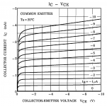
BTW, I made a mistake, the horizontal scale of the 7CT1N curves I posted a couple days was actually 500mV/div, not 2V as I labeled it.
Last edited:
kozard -did anyone answer yhour earlier question about loops?
It's caused by the capacitance (Cjc mostly). So one transistor with a bigger loop has a bigger capacitance than another.
Interesting. So while the low current linearity looks good for the generic 2SA970 the capacitance is (significantly?) larger.
I am busy with my DAC/ADC projects right now but maybe later in the year I can look at making a curve tracer again. However it sounds like my DIY curve tracers (based upon Arduino) will be oblivious to this looping/capacitance. It sounds like I should combine it with capacitance measurements when checking out the "generics".
Member
Joined 2009
Paid Member
I remember guidance from Jean Le Hiraga for small signal transistors is setting their operating point at the peak of their Hfe which tends to be a 'convex' shape on the graph.
The other person who's advice I found interesting was Vladimirk in his Rails Decoupled Amplifier thread. He mentioned that output devices operated such that they show increasing beta produced the best bass as they 'want to give current' when under demand. He is also a fan of very low capacitance, looking for transistors that are more like vacuum tubes.
The other person who's advice I found interesting was Vladimirk in his Rails Decoupled Amplifier thread. He mentioned that output devices operated such that they show increasing beta produced the best bass as they 'want to give current' when under demand. He is also a fan of very low capacitance, looking for transistors that are more like vacuum tubes.
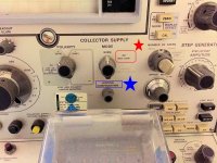
DIYers interested in loops on the CRT display of old style ACmains powered curve tracers, might want to check what Tektronix has to say about it:
http://www2.ensc.sfu.ca/~glennc/e495/576curvetracer_user.pdf
Here's mine:
_
http://www2.ensc.sfu.ca/~glennc/e495/576curvetracer_user.pdf
Here's mine:
_
Attachments
So the context of the question was why a Toshiba 2SA970 showed no looping yet a generic 2SA970 showed looping on the same curve tracer with the same settings.
So my question was whether the generic 2SA970 was different in a detrimental way to usage as a substitute for genuine Toshiba 2SA970.
I have read page 2-22 in the 576 Curve Tracer manual. At this point I am concluding (in the context of the question) that the generic 2SA970 is exhibiting either much larger capacitance or much higher thermal effects than the Toshiba.
I don't know which and unfortunately my meter is not very helpful at measuring single digit pF capacitances. Toshiba lists 2SA970 Cob as 4pF.
Hi Guys
did I miss something? I cannot see if Jbau posted the results for the 2SA970
Regards
Mike
did I miss something? I cannot see if Jbau posted the results for the 2SA970
Regards
Mike
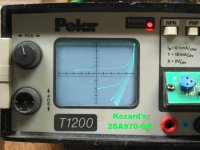
I sent him the pics but didn't post them. This is the "Generic" 2SA970 kozard sent me, along with it's complement 2SC2240. Both "GR" spec.
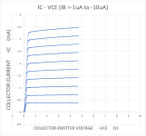
I also tested them at lower Ib with the Tek 7CT1N. The 970 is very linear at 20-25uA and below, at Vce of 5V and above.
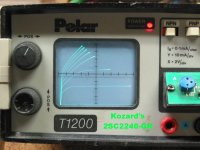
It's mate 2SC2240 linearity is a bit better, good up to 30uA or so. This is probably due to it's Hfe being a bit lower, 250 vs 320.
I also tested them at lower Ib with the Tek 7CT1N. The 970 is very linear at 20-25uA and below, at Vce of 5V and above.
It's mate 2SC2240 linearity is a bit better, good up to 30uA or so. This is probably due to it's Hfe being a bit lower, 250 vs 320.
Attachments
Hi again
thanks for that Jbau.
I was planning on plotting some curves with my Peak tester in the next few days. If I can figure out how to get a screen shot, I'll post them back here for comparison.
thanks for that Jbau.
I was planning on plotting some curves with my Peak tester in the next few days. If I can figure out how to get a screen shot, I'll post them back here for comparison.
Sounds good Mike, I look forward top seeing them.
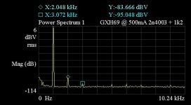
I just applied similar mods to one of my JLH69 amps as I did to the JLH headphone amp. Changed driver NPN from 2N1711 to 2SC1318 (same Hfe, better linearity); changed input PNP from 2N2907A to 2N4403 (same Hfe, better linearity); optimized the input R for 2VRMS into 25 Ohms (this one drives electrostatics). Optimum R was 1k0 to 1k2 (plus pot R).
The result was a 9dB drop in H2 to -90dB, and H3-H10 to below -100dB !
I stopped using this amp because the LM3886 amps I built sounded so much better. My bet is, this will reverse that outcome.
Attachments
because the LM3886 amps I built sounded so much better.
Which circuit, jbau?

Which circuit, jbau?
Complete chip amp kit with enclosure, etc ?
As expected, with the more-linear transistors, the JLH's sound fantastic with my Stax SR-X, and the 3886 amps have officially been displaced. There's just no comparison in clarity and openness now. This was with an old Lambda linear supply with low-BW regulation which I know from prior listening is not all that great.
Into 25 Ohms, they still like to see 500mA bias for a 25 Ohm load. I was hoping to be able to lower that to lessen heat generation.
Next is to optimize the little TIP41C-based 3W modules. That's plenty of power for these 'stats, and their smaller footprint would be nice, they should be good for 32-Ohm dynamic headphones too.
Complete chip amp kit with enclosure, etc ?
As expected, with the more-linear transistors, the JLH's sound fantastic with my Stax SR-X, and the 3886 amps have officially been displaced.
Ok, thx jbau. You're lucky to have such headphone to review your electronics by ears.
Yes, I suppose so. The SR-X are very good, but in stock form the Stax transformer adaptors are really awful. Some of the worst audio engineering I've ever seen (ex: a thermistor in series with the signal as an input protection device!) and take a lot of work to make transparent. Quite amazing that they were so well liked. I'm going to make a webpage with the mods at some point.
They do appear for reasonable money now and then. Unfortunately there are collectors who horde vintage Stax and drive the prices up.
Last night I replaced the old Lambda linear supply with the Lambda switcher I used earlier and it is definitely better. And runs cooler.
They do appear for reasonable money now and then. Unfortunately there are collectors who horde vintage Stax and drive the prices up.
Last night I replaced the old Lambda linear supply with the Lambda switcher I used earlier and it is definitely better. And runs cooler.
Last edited:
I sent him the pics but didn't post them. This is the "Generic" 2SA970 kozard sent me, along with it's complement 2SC2240. Both "GR" spec.
I also tested them at lower Ib with the Tek 7CT1N. The 970 is very linear at 20-25uA and below, at Vce of 5V and above.
It's mate 2SC2240 linearity is a bit better, good up to 30uA or so. This is probably due to it's Hfe being a bit lower, 250 vs 320.
So I received the parts back and the below graphs are first the Toshiba datasheet curves and then my first attempt at a homebrew curve tracer measurement of the generic 2SA970.
Attachments
I tried to match a few TTC5200 with a higher collector current of about 500mA (24V) or so, but presumably because of the changing temperature, the collector current did not stabilize for a long time. The transistor was on a heat sink. How do you match output transistors? Just use a bigger heatsink for the temperature to stabilize and wait for 10's of minutes?
my first attempt at a homebrew curve tracer measurement of the generic 2SA970.
You work fast! Results lookin' good.
Hello Hanair, I used independent heatsinks. 1 for each transistor. Their measurement is: 9.5cm x 11cm x 5cm
If you are putting it in a single heat sink, (Q1 and Q2) you can use it next to: 19cm x 11cm x 5
Tiago Sierra
Have you followed the schematic exactly as shown in the following post?
JLH 1969 Explanation
I am building a JLH1969 on a new PCB using TTC5200 and noticed severe oscillation. I had to use 1.5nF between collector-base for both output transistors to get it working but that severely limits the bandwidth. I also substituted 2N4403 instead of 2N3906 and 2N4401 instead of 2N1711.
- Home
- Amplifiers
- Solid State
- JLH 10 Watt class A amplifier