8018 Current shown from 0.01A (10mA)?
The area of microcurrents (less than 0.1-1mA) is determined separately.
The area of microcurrents (less than 0.1-1mA) is determined separately.
Last edited:
Wow, exceptional. And in EOL last-time-buy status.
I took scree-capture images this morning, at the websites of (a) ON Semiconductor, and (b) octopart dot com.
_
Attachments
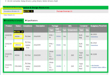
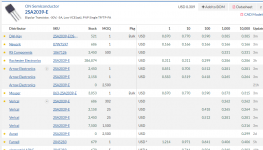
I took scree-capture images this morning, at the websites of (a) ON Semiconductor, and (b) octopart dot com.
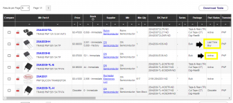
Hmmm. Digikey says "Part Status: End of Life; Last Time Buy Date: 7/5/2021. Minimums may apply."
Yes that's NOTE 3 in post #8023. Lifetime buy on (both lead free AND halide free). However (only lead free) is still in active production at ON Semi, see NOTE 2 in post #8023. Digikey agrees, see below.
Depending on how you personally feel about halide-free transistors, there might or might not be an urgency.

_
Depending on how you personally feel about halide-free transistors, there might or might not be an urgency.
_
Attachments
Last edited:
Looks like a good driver, too.
It's compliment 2SC5706 also looks good, but linear-beta NPN's have been much easier to find.
It's compliment 2SC5706 also looks good, but linear-beta NPN's have been much easier to find.
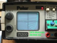
JLH specifically shows the Motorola 2N3906 as the input device in his first paper. I wondered, what were the 3906's like that he had access to?
I found six of them on an old pcb (socketed, conveniently) with the date 05/1970 etched on the solder side. Five of them were pretty much the same, Hfe of ~135, shown in the first pic. The other was 200 Hfe, shown in the 2nd pic.
At Vbe of about -8V and up, the first one has good beta linearity up to 300uA Ib, then sags.
The higher Hfe one isn't nearly as good.
Just thought I'd post this for historical context.
Attachments


The choice of si pnp transistors in the 70s was limited. For the phase splitter, there was a larger selection of npn transistors.
Last edited:
Another successful optimization of max input signal level, device linearity extension, and optimum source resistance results in a 2N4403 displacing the KSA1015Y:
JLH Headphone Amp
Next is to apply this to the JLH '69 amps.
JLH Headphone Amp
Next is to apply this to the JLH '69 amps.
Interestingly, (or coincidentally) looking at the 2N4403 data sheet, the optimum source resistance for minimum noise is in the 2K Ohm area when running at 50uA collector current @1KHz.
Wide(r) band optimum Rs is 2.7K Ohms with a Ic of 50uA.
I am sticking with the 2SA970 as it sounds good to my ears and has the high voltage Vceo for my high power JLH. But would be interested to see the test results you get for the '970 when you get a couple from Kozzard.
Mike
Wide(r) band optimum Rs is 2.7K Ohms with a Ic of 50uA.
I am sticking with the 2SA970 as it sounds good to my ears and has the high voltage Vceo for my high power JLH. But would be interested to see the test results you get for the '970 when you get a couple from Kozzard.
Mike
Yeah, I saw that coincidence in ON Semi's data sheet; it's not on the old Fairchild sheet. This one is actually running closer to 3k Ohms total (we have to add the nominal 1k Ohm volume pot output R). I'm going to try a 1k8 series R at some point, it was the bottom end of the optimum range, and H2 was a tad better there. But by 1k5 you could see the harmonics just starting to creep up, and at 1k0 they were all clearly rising.
John Curl was one of the first people to notice that the 2N4401/4403 complementary pair would be excellent for audio uses. He even included those specifc parts in his 1976 patent (column 2, line 25) of a moving coil pre-preamp circuit.
Here is a link to the patent, it is number 4035737A in the United States.
Here is a link to the patent, it is number 4035737A in the United States.
That's interesting. Their betas do match up very well, I've noticed. Kudos to JC !
On my list for today is to find the 8099/8599's I know are here somewhere...
On my list for today is to find the 8099/8599's I know are here somewhere...
jbau put a lot of effort into measuring some of my generic devices.... Now I have a number of questions about the results.
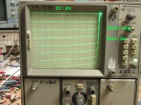
The first question is regarding looping in the back trace. What is the physical cause of this?
The attached examples are first a generic 2SC1815 (with the loop back apparent) and then an original Toshiba 2SC1815 without the looping on the back trace.
The first question is regarding looping in the back trace. What is the physical cause of this?
The attached examples are first a generic 2SC1815 (with the loop back apparent) and then an original Toshiba 2SC1815 without the looping on the back trace.
Attachments

Last edited:
Hi everyone. Been a little while since I visited but time to move forward with my JLH 69 project. I was going to do point to point wiring on my amp boards originally but have decided to just use my own components on a pre-made PCB. There are many cheap versions on ebay and aliexpress. My only concern is that the tracings may not be up to scratch for the quiescent current. Has anyone had experience (good or bad) with a particular seller?
Here are 2 that I found. From a quick glance they seem flexible as far as components. I will be using 3300uf output cap and mj15003 mounted on proper separate heat sinks, not in a piece of aluminium angle as shown in the pictures which seems totally inadequate. Any comments? Do the layouts look ok?
https://m.aliexpress.com/item/40009...15797233-01186-UneMJZVf&device=m&gclsrc=aw.ds
1pcs 1969 Power Amplifier Board Class A Power Amplifier Board PCB DIY | eBay

I was unable to find the missing MPS8099/8599's so I guess I have to accept they're long gone.
Instead, I pulled out the Tek 7CT1N curve tracer plugin that has been waiting since 2006 for me to fix. Found one open electrolytic, one shorted transistor following it, and one open pot. Replaced them and it's back in business. Having this could be enough motivation for me to put the ol' 7603 back on the bench. My aging eyes love the big display.
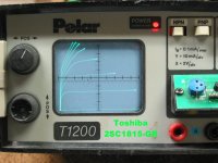
So I spent some time looking at the low-current linearity of numerous small-signal transistors. The little Polar tracer is fixed at 100uA/step and 10mA/division. This goes down to 1uA/step. Probably won't use that much; a more useful range is 5 to 10uA.
Most of the transistors I looked at were pretty linear in the low range. NPN's more so than PNP's. Even the super-beta ones were linear up to 10uA Ib, some 20uA. And then the beta starts tailing off, some more rapidly than others. The 2N5087 is linear only up to 10uA.
One oddball was the MPS6534. It has a very gradual beta gain all the way up to about 200uA where it started it's droop. It's complement 6531 is very linear.
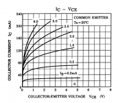
Here's a pic of a Toshiba 2SA1015-GR, sought after and widely used on the input of JLH's. This one is only 220 Hfe, which is on the low end of the GR spec. But even it shows the "early beta droop" that nearly all of the high-beta devices do. Linearity is good below about 5mA Ic. Higher than than, it becomes somewhat Vce-dependent. At 16mA Ic, Beta is already 10% down at Vce=10, but only 3% down at Vce=16. A higher-beta 1015 will be even worse.
This slow, constant "Beta sag" may be what gives this device it's warm, smooth sound. It's complement 2SC1815 is very linear and shows no such droop, up to 250uA Ib.
A cool new tool always makes me wanna measure everything in sight 🙂
Instead, I pulled out the Tek 7CT1N curve tracer plugin that has been waiting since 2006 for me to fix. Found one open electrolytic, one shorted transistor following it, and one open pot. Replaced them and it's back in business. Having this could be enough motivation for me to put the ol' 7603 back on the bench. My aging eyes love the big display.
So I spent some time looking at the low-current linearity of numerous small-signal transistors. The little Polar tracer is fixed at 100uA/step and 10mA/division. This goes down to 1uA/step. Probably won't use that much; a more useful range is 5 to 10uA.
Most of the transistors I looked at were pretty linear in the low range. NPN's more so than PNP's. Even the super-beta ones were linear up to 10uA Ib, some 20uA. And then the beta starts tailing off, some more rapidly than others. The 2N5087 is linear only up to 10uA.
One oddball was the MPS6534. It has a very gradual beta gain all the way up to about 200uA where it started it's droop. It's complement 6531 is very linear.
Here's a pic of a Toshiba 2SA1015-GR, sought after and widely used on the input of JLH's. This one is only 220 Hfe, which is on the low end of the GR spec. But even it shows the "early beta droop" that nearly all of the high-beta devices do. Linearity is good below about 5mA Ic. Higher than than, it becomes somewhat Vce-dependent. At 16mA Ic, Beta is already 10% down at Vce=10, but only 3% down at Vce=16. A higher-beta 1015 will be even worse.
This slow, constant "Beta sag" may be what gives this device it's warm, smooth sound. It's complement 2SC1815 is very linear and shows no such droop, up to 250uA Ib.
A cool new tool always makes me wanna measure everything in sight 🙂
Attachments
Last edited:
A cool new tool always makes me wanna measure everything in sight
Maybe remeasure the 2SA970/2SC2240 combo with 1uA steps🙂?
- Home
- Amplifiers
- Solid State
- JLH 10 Watt class A amplifier