Interesting. Would be nice if they provided some AC specs, too.
BTW, your avatar reminds of the graphic on my favorite T-shirt. IIRC, it comes from the symbol on the national flag of a small country in South America (can't remember which). I should probably use it 🙂
BTW, your avatar reminds of the graphic on my favorite T-shirt. IIRC, it comes from the symbol on the national flag of a small country in South America (can't remember which). I should probably use it 🙂
Attachments

Last edited:
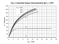
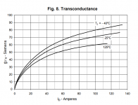
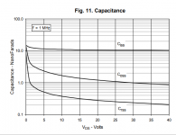
Power Mosfet.Here are some modern (introduced 2011) power transistors which are specifically designed to implement constant current electronic loads: (link)
You might enjoy this excellent JLH explanation. Type 4 should be out of the question, but isn't. 55 dB open loop gain is excellent considering how simple the circuit is. Output stage distortion is circa 3% which will depend on devices used. 20 dB feedback offerers circa 0.3%. I actually saw 0.03% using very cheap OK parts at 5 watts. My main doubt being output device capacitance and need to tune the amplifier for stability. I used point to point construction and BC327/337-40 and Indian 3055 (E).
https://www.firstwatt.com/pdf/art_plh.pdf
https://www.firstwatt.com/pdf/art_plh.pdf
I did measure the open loop gain. More or less exactly as stated. John Ellis suggested the output stage distortion. I had no problem getting the suggested values. Modern amplifiers have open loop gains of perhaps > 80 dB. 55 dB is not too shabby for the JLH. If someone could live with a gain of 2 doubtless the distortion would be incredible ( check stability, nicer feedback lower arm ). If so a pre amp headphone amp could be made with 5 Vrms output.
Has anyone used a complimentary feedback pair as a JLH VAS/ Phase splitter? It could have similar DC points whilst being more linear. Current drive should be good. I tried this with another amplifier with few problems! I think using a local feedback capacitor helped ( 33 pF )
Has anyone used a complimentary feedback pair as a JLH VAS/ Phase splitter? It could have similar DC points whilst being more linear. Current drive should be good. I tried this with another amplifier with few problems! I think using a local feedback capacitor helped ( 33 pF )
Harmonic distortions are reduced if you use an additional OE amplification stage Vas and an inverted phase splitter pnp (like in Brosky / Nikitin).
http://forum.vegalab.ru/attachment.php?attachmentid=391652&d=1614460621
http://forum.vegalab.ru/attachment.php?attachmentid=391652&d=1614460621
Last edited:
My idea of a current boosted op amp in class A almost is a zero distortion option. The JLH probably sounds better as it's harmonic progression is more like how the ear works. Either solution sounds good. I would suggest anything between doesn't. By zero distortion I mean better than -110 dB H2.
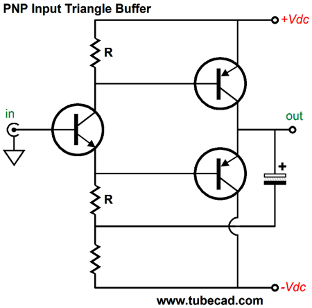
Do you have the tube cad link for that? It's nice to find a tube man who looks for transistor circuits of similar type. My favourite tube idea is Futtermans and the Philips TV amps of similar type using high Z speaker. The Croft is a variation.
If someone could live with a gain of 2 doubtless the distortion would be incredible ( check stability, nicer feedback lower arm ). If so a pre amp headphone amp could be made with 5 Vrms output.
That is pretty much what I am exploring. By lowering gain to 5, and choosing outputs that have a more linear gain curve, H2 has gone from -68dBr to -80dBr. Interestingly, H3 has stayed constant around -94dBr. That is probably at the limits of my 16-bit measuring system.
Perhaps a Hall notch filter (and perhaps an LNA after the notch filter) would help extend the limits of a 16-bit measuring system.
I made a notch filter 11-12 years ago, but the primary limitation in this system is the DAC. (DAC development lagged behind ADC's in the early days). If the system wasn't so useful for other things, I'd replace it. For now, I figger any power amp that reaches the system's limits is bound to sound pretty good...
That is pretty much what I am exploring. By lowering gain to 5, and choosing outputs that have a more linear gain curve, H2 has gone from -68dBr to -80dBr. Interestingly, H3 has stayed constant around -94dBr. That is probably at the limits of my 16-bit measuring system.
I have this problem. As a rule these things are mathematically predictable. The reason triangle waves are used is they approximate music better than square waves. Square being F +1/3f3+1/5f5+1/7f7+1/9f9....... Triangle being F +1/9f3+1/25f5+1/49f7+ 1/81f One can see a triangle wave is a square wave passed through a perfect 1st order filter due to squared harmonics displayed as values ( ie f7 and 1/49 ).
Hiraga's 1980s conjecture was a simple exponential value likely was the best description of the ideal curve. The workings of the ear are similar. He said a straight line rule could be argued but instinctively thought less likely. He noticed raised f3( H3 ) sounds faster. Naim amplifiers mildly are this due to 1 to 22K long tail pair balance. The 22k pushes up H2 to mimic a singleton transistor. If 22K made 33K H2 would move up. The Naim is more JLH/Quad 303 than modern Cambridge.
A sawtooth has a mild resemblance to this curve if only as numbers. F+ 1/2f2+1/3f3+1/4f4+1/5f5+1/6f6+1/7f7+1/8f8+1/9f9........
On the oscilloscope the JLH wave is seen as more pointed on one cycle side. it will be seen more obviously if feedback is reduced. .
Taking 16 bit. 16 x 6.020dB/bit is 96.3 dB. Rosen would set the reliable range as 76 dB. Rosen suggested better -116.3 dB from a Wien oscillator to measure prototype 16 bit CD. Most measuring systems have things like dither to enhance what we get. Cyril Bateman adapted this idea to measure capacitor distortion which generally needs 24 bit in the modern world. Cyril and others feel this valid. He adapted the Rosen SVF oscillator. 6.0206 is 20log base 10 of 2 per bit ( 20 x 0.301103 )
24 bits is 144.5 or 122.4 Rosen. Hiss comes into this.
Cyril Bateman's Capacitor Sound articles | Linear Audio NL
24 bits is 144.5 or 122.4 Rosen. Hiss comes into this.
Cyril Bateman's Capacitor Sound articles | Linear Audio NL
In a 1969 amplifier, you can reduce the collector voltage of the input transistor by dividing the pull-up resistor by two.
The top one can be shunted with a boost capacitor.
The noise can be reduced.
The top one can be shunted with a boost capacitor.
The noise can be reduced.
Taking 16 bit. 16 x 6.020dB/bit is 96.3 dB. Rosen would set the reliable range as 76 dB.
That is hyper-conservative, and appears not to take advantage of the benefits of averaging. With only 64 spectrum averages, my 16-bit system (which has excellent programmable preamps) has a dynamic range of -110dBr, with good repeatability resolving spectrum features in the -90dB to -100dB range.
It's possible one could do even better than that using time-domain averaging using a hardware trigger from the DAC, but I haven't explored that in this situation. It does wonders in acoustical measurements.
I agree with that. As you say, when a reading stays the same doubtless it's reaching the buffers.
Very early 16 bit systems had 30 % THD using the last two bits. This improved to 3% when dither was added. Mike Creek by accident made an amplifier with no bias. A true class B. It actually sounded not too bad. Mike said the amplifier having some hiss seemed to be dithering the output. When the fix was made the sound was warmer and more dynamic. JLH being class A won't respond to that.
Very early 16 bit systems had 30 % THD using the last two bits. This improved to 3% when dither was added. Mike Creek by accident made an amplifier with no bias. A true class B. It actually sounded not too bad. Mike said the amplifier having some hiss seemed to be dithering the output. When the fix was made the sound was warmer and more dynamic. JLH being class A won't respond to that.
- Home
- Amplifiers
- Solid State
- JLH 10 Watt class A amplifier