I forgot to mention one thing I find positive when simulating the floating ground, is the current draw from the PS. The current variations from the PS are very small when the amp is driven, compared to standard grounding.
Have you simulated the transient response (low frequency) of the floating ground arrangement?
I also had a design once (class AB) using the floating ground ... until I simulated it.
I found that decoupling the supply lines with a large capacitor helped. That means adding a 10k equivalent to R16 in the - line and something like 1mF each to ground.
I did some tests in LTspice.
First I concluded that here is no oscillation without input connected, so the LF oscillation seems to be from feedback to the input via the floating ground.
Using the idea from Bigun as inspiration, I made another floating ground for the input with two capacitors from the rails, and then connected that via a resistor to the common ground. This removes the LF fluctuations on the input GND, but keeps it on the same DC level, after that there was no LF oscillation at startup.
From Bigun
Yes, larger capacitors do not eliminate the risk of LF instability. In the design I looked at they did push the LF bounce to such a low frequency that it was not triggered by audio signals, and the amplifier became usable, as opposed to not.
I've simulated it before and it requires a large amount of capacitance and it suffers from the same risk of low frequency instability as a single output capacitor - as you would expect.
Yes, larger capacitors do not eliminate the risk of LF instability. In the design I looked at they did push the LF bounce to such a low frequency that it was not triggered by audio signals, and the amplifier became usable, as opposed to not.
Just thought I would upload the sim I made of my PNP JLH with floating ground. As mentioned before, the small signal transistors are not the same as in the ZeroZone kit, but it simulates very close to reality when it comes to distortion levels and spectrum.
Attachments
Rallyfinnen,
you have been developing a finished product for over a year now. What troubles are you struggling with if I may ask?
you have been developing a finished product for over a year now. What troubles are you struggling with if I may ask?
I will answer that. Sometimes you see a conflict in a design and feel something better is there. Often the more you try the future away it gets. Personally I would try to get harmonics falling on a suspension bridge curve. Getting the current gain of each transistor as high as possible and find ideal current by ear. Then choose capacitor time constants. Power supply iif possible old school.
Rallyfinnen,
you have been developing a finished product for over a year now. What troubles are you struggling with if I may ask?
I have a habit of tweaking things. I have been into tuning engines, modifying speakers, cars, mopeds, motorcycles, RC-cars and so on. Also racing with cars and RC-cars. It's what I do for fun, a hobby, that's my only defense! 🙂
I have built several versions of this amp, and they all sound a little bit different, and measure different too. Playing around with the JLH is a way to learn about amps, simulation, correlating measurements with what I can hear etc. Seems like a good place to start, since it has only a few components. One year ago I had no clue how it worked, or how to simulate it, now I know a little bit more.
I would compare it with a two stroke engine, simple design with a few moving parts, but takes a lot of effort and understanding to get the most of it.
Last edited:

I think the amplifier is far more complicated than it looks. The opperation of the two output transistors my greatest doubt. Douglas Self approximately says that the current division is vague.Self likes things to be black and white. I never remember him saying how a thing sounds or if he did it's when very wrong.
Hmmmm interesting.
I said I would post back the results of simulating John's suggestion of modifications to the 'Mod 5' S-pair JLH and they make for very interesting reading.
I had a couple of challenging 'failing of faith' moments which turned out to be finger trouble and if anyone find glaring mistakes, please let us all know and share the knowledge
I suggest you start by reading the results table in the Excel spreadsheet to see how the differing changes made what difference. I found them quite educational and significant food for thought - there were a couple of oscillating changes that necessitated 47pF slugs around the main driver Q3 especially when a BD 139 was used in this position.
I started by pulling the quiescent current back from the somewhat extreme 2A per pair (a total of 8A Iq) - that was my mistake to start with. 🙁
So, as in my original NPN 4 pair model, I set each of the PNP power devices with 750mA going through them. I then added changes one by one and recorded the results so as to see what did what. Changing the current down made the first significant difference.
I also swopped out the BD139C model for the LT BD139 model and after moving things around to get to Johns final circuit, I changed the current sharing resistors down from 0.68r to 0.22R.(this latter move didn't make that much difference)
The final couple of changes included adding the auxilliary rail of 22 volts and increasing the input transistor's Collector load to 68k (plus the catching diode on the base of the driver) made a very significant drop in THD, although I haven't looked at the harmonic structure on a FFT yet. Hats off to John for that one.
So having got that final version all hunky dory, I played around with increasing the Iq to see its effect on the THD - the results are that it is not worth going above Iq of 3 Amps - in the simulation that is, particulary at low power.
I suspect that I have made a mistake somewhere as the theoretical Iq should be about 6 amps to get to the stage where the amp clips on the rails (as opposed to being current starved) so if anyone can point that out I would be grateful.
So have a play, I think this is something to be built either as a single pair with lower rails (or as a the behemoth in the simulation) and seriously listened to.
Usual caveats: it is only a simulation, batteries not included, your mileage may vary etc.
Kind regards
Mike
Attachments
I had this PNP JLH apart the other day to replace the bootstrap cap with a larger one, so I updated the schematic with that, and also found an error: I have no feedback cap in the amp, so I removed it from the schematic too.
I can't say I can hear any difference with the lager bootstrap cap, but I do love the sound from this amp! I noticed a significant improvement in sound when I switched back to this one from another JLH.
I have same amplifier, i replace its original noisy psu with a better powerfull one same voltage 24v by the way but it get toasted in a second. Something wrong with this design.
I don't think there is something wrong with the design, it's basically the same proven 1969 design, only mirrored and PNP outputs. This is my favorite amp so far.
Rallyfinnen,
the JLH 1969 amp can certainly be improved. Would you embark on my version?
Not sure.. I try to stick to simple mods, since I don't make PCB's etc. Is your version on the forum here somewhere?
Hmmmm interesting.
I said I would post back the results of simulating John's suggestion of modifications to the 'Mod 5' S-pair JLH and they make for very interesting reading.
I had a couple of challenging 'failing of faith' moments which turned out to be finger trouble and if anyone find glaring mistakes, please let us all know and share the knowledge
I suggest you start by reading the results table in the Excel spreadsheet to see how the differing changes made what difference. I found them quite educational and significant food for thought - there were a couple of oscillating changes that necessitated 47pF slugs around the main driver Q3 especially when a BD 139 was used in this position.
I started by pulling the quiescent current back from the somewhat extreme 2A per pair (a total of 8A Iq) - that was my mistake to start with. 🙁
So, as in my original NPN 4 pair model, I set each of the PNP power devices with 750mA going through them. I then added changes one by one and recorded the results so as to see what did what. Changing the current down made the first significant difference.
I also swopped out the BD139C model for the LT BD139 model and after moving things around to get to Johns final circuit, I changed the current sharing resistors down from 0.68r to 0.22R.(this latter move didn't make that much difference)
The final couple of changes included adding the auxilliary rail of 22 volts and increasing the input transistor's Collector load to 68k (plus the catching diode on the base of the driver) made a very significant drop in THD, although I haven't looked at the harmonic structure on a FFT yet. Hats off to John for that one.
So having got that final version all hunky dory, I played around with increasing the Iq to see its effect on the THD - the results are that it is not worth going above Iq of 3 Amps - in the simulation that is, particulary at low power.
I suspect that I have made a mistake somewhere as the theoretical Iq should be about 6 amps to get to the stage where the amp clips on the rails (as opposed to being current starved) so if anyone can point that out I would be grateful.
So have a play, I think this is something to be built either as a single pair with lower rails (or as a the behemoth in the simulation) and seriously listened to.
Usual caveats: it is only a simulation, batteries not included, your mileage may vary etc.
Kind regards
Mike
Looks like the distortion spectrum is falling, typical JLH.
I don't think there is something wrong with the design, it's basically the same proven 1969 design, only mirrored and PNP outputs. This is my favorite amp so far.
I have these boards, default off load voltage source is 26.7v. I connect same board much clean 22v and it get burned in a second. What could be wrong?
Almost all componenets on it is obsolete. 2SA1216, 2sa1145, 2sc2705.
Which PNP version you use?
Attachments
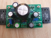
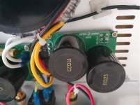
Attached a picture of my modified PNP bords. I think it's the same amp, only that mine came with rectifier and caps.
Not easy to say what went wrong. Can't see any burned components on the board either. Did you check the current setting when you changed the supply?
Current changes when voltage is changed.
You could try to measure the components, since there are not so many.
Not easy to say what went wrong. Can't see any burned components on the board either. Did you check the current setting when you changed the supply?
Current changes when voltage is changed.
You could try to measure the components, since there are not so many.
Attachments
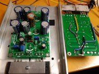
Attached a picture of my modified PNP bords. I think it's the same amp, only that mine came with rectifier and caps.
Not easy to say what went wrong. Can't see any burned components on the board either. Did you check the current setting when you changed the supply?
Current changes when voltage is changed.
You could try to measure the components, since there are not so many.
what i saw transistors are different your board uses a970 and c2240 i guess
I just put together a JLH 69 version with cap coupled output. Only change I made was a 2N5088 input transistor, Tr4 and 220K resistors for the Base of Tr4. Tr3 was a TI 2N1711 from 1980 and outputs were 2N3055 from ST (recent but can't decipher their date codes). I had a low level oscillation that quit when I added the fixes from the Wireless World December 70 article.
I didn't build a cap multiplier, used a simple cap filter 12000uF. After I took some measurements on the AC and lab power supplies, I installed the active current source for Tr3 from 2003. I split the resistor to ground and installed a cap to the plus rail. I used 2N4036 and 2N2907. That reduced THD in the 100mW area by about half but still not as good as the lab power supply. Guess I'll have to build a cap multiplier.
I didn't build a cap multiplier, used a simple cap filter 12000uF. After I took some measurements on the AC and lab power supplies, I installed the active current source for Tr3 from 2003. I split the resistor to ground and installed a cap to the plus rail. I used 2N4036 and 2N2907. That reduced THD in the 100mW area by about half but still not as good as the lab power supply. Guess I'll have to build a cap multiplier.
Attachments
Looks like you have expensive test equipment 🙂
A short summary of my findings when it comes to JLH 69 distortion(maybe I'm repeating what you already know):
If you had played around with the base resistors for the upper transistor in the 69 version (without ccs), I think you could have improved the distortion readings. Balancing the resistors on each side of the bootstrap cap adjusts the current modulation of the upper transistor and can have significant effects on distortion (and current output).
Balancing them decreases 2nd order distortion most, but also other orders, and IMD.
Increasing the bootstrap capacitance can also improve the current sharing at LF, and thus increase current output and reduce distortion in the LF area. I guess in theory, a small output cap can also add some capacitor distortion at LF. Same goes for input cap.
Most output transistors also work best with a specific Iq, keeping them in the most linear working range, so that can also be played around with.
0.00x% should be possible with some tweaking, but maybe not with the 3055. I have seen figures like that in Arta around 1W into 8ohm load, but I prefer to look at the FFT and not plain numbers. EDIT: not sure now, maybe it was only 0.01 something.. anyway, distortion around -90dB is definitely possible.
Last edited:
Great to hear that the JL-H is still arousing interest.Split rail amp. is much better,eliminates the op. cap. Tried building the amp. with Toshiba 2SC5200s (watch out for fakes!). The sound was extremely "bright",not surprising as the op. was still flat at 250KHz.!It is well worth reading the JL-H section on the Class A Amp. Site. now hosted by Elliott Sound Products.
- Home
- Amplifiers
- Solid State
- JLH 10 Watt class A amplifier