Correction
In the last sentence I slipped up - I should have said the gain is directly proportionate to the temperature on the Kelvin scale.
With regard to the effects of heat on transistors, the simplest explanation is this works to loosen the bonds which keep electrons attached within the crystalline structures which more frees electrons allowing more current to flow.
Specification sheets quantify current gain at room temperature 25 degrees C. The gain is inversely proportionate to the temperature on the Kelvin scale of 298.15 degrees.
In the last sentence I slipped up - I should have said the gain is directly proportionate to the temperature on the Kelvin scale.
The thing to study is band gap. LED's range in voltages between 1.6 to 4.5 volts approximately, as with heat red takes less energy ( it seems likely for the same reason, think old style lamp ). Silcon transistors about 0.6V. Some special diodes can be used for radio tuning. They give in suitable bias variable capacitance at different voltages. Zener diodes are very interesting. The zener effect is common to most silicon devices. LED's are good band gap voltage references. A red LED about 3 times better than a 1N4007 from memory.
I realised recently that all conductors must have a bandgap. Some say the same. Copper is so close to 0V it usually is of no value to state it.I would guess true super conductors if temperture is low enough must have a 0V band gap. These things often are not that easy to define.
The LED gives off light as the electron moves back to the chemical valancy band from the conductance band. The band gap of some materials is almost infinite. These make very good capacitors. Heat conduction is linked to the same qualities. The main differnce is heat can be stored in metals. From this point on much is not known. Aluminium is not obviously a good conductor, that is until mass is factored in. Aluminium should be a near insulator if being lazy with theory. Some call it a metaloid.
I should add that a high band gap material like polyester and a good conductor like aluminium ( ? ) make a good capacitor. When so a limited quantity of charge can be stored in the capacitor ( negatively charged and positively charged, almost like holes in transistors ). A bar of red hot metal stores energy better. A hot body of metal has a higher electrical resistance usually. Some compound metals do the opposite. Some compounds almost have constant resistance with temperature. Transistors mimic the compound metals. It is surprising how good a semiconductor conducts as it is mostly an insulator. By adding a remarkably small quantity of impurity it can conduct once the band gap is reached. It is hard to believe how good a conductor this can be. Locomotives uses semiconductors to regulated megawatts of power.
Solder is interesting. Some solders with the right ratio of tin and lead have lower melting points than either metal !! This proves that in many ways this is a new metal with many qualities of a pure metal. That's Alchemy. Gold and Mercury are interesting. It is thought they originate in Super Nova. It seems Mercury is more common. This may not be true as the planet may hold it's gold in the core. The other idea is that mercury is the prefered Super Nova result as it is more symetrical.
Solder is interesting. Some solders with the right ratio of tin and lead have lower melting points than either metal !! This proves that in many ways this is a new metal with many qualities of a pure metal. That's Alchemy. Gold and Mercury are interesting. It is thought they originate in Super Nova. It seems Mercury is more common. This may not be true as the planet may hold it's gold in the core. The other idea is that mercury is the prefered Super Nova result as it is more symetrical.
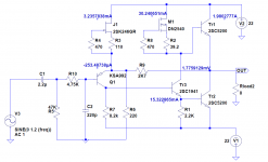
For cooler running I would limit the supply rails to +/- 22Volts which is the point I started out with the simulation I am posting. The idea to use MJL3281 super beta output transistors was to reduce the current demand on the split phase transistor - a 2N5551 in this instance.
This is rated variously at 625 m.W. (or 1W in an old Motorola Small Signal Databook) I have a couple of Motorola 2N5551's in my old stocks. In the simulations here the median dissipation is about half of the lower figure.
There is a version of this device where the collector and emitter leads are crooked out to fit wider track spacing. This allows the pads on the copper side of a pcb to be a little larger. In theory some of the heat in the body of the transistor will travel down through the leads into the copper of the pcb.
If dissipation in this transistor becomes an issue with a requirement for high output current levels then 2SC 3503 or KSC 3503 would give a close enough result.
The latter and 2N5551 are not available over the counter in electronics stores and there are no major warehouse suppliers where I live. Some of these will sell only in minimum quantities like 200 which I regard as a turn off.
There is another option use a 2N3904 and cut down on the output current and power level to a little bit more than the 1969 Class A which should be adequate with reasonably sensitive speakers and more than enough with some of the larger and more sensitive ones.
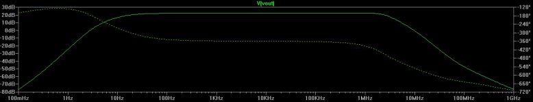
The simulation attached is to determine the stability margins. In this R5 and R14 need to be variable for adjusting dc offset and output current. R10 connects to the negative rail rather than earth. The intention here is to allow a thermal cut out to be mounted on a heat sink to turn the amplifier off if it gets too hot - or otherwise if the negative rail fails the constant current sources will be disabled and avoid a dc fault on the output line.
To run the simulation copy the expression in blue on the .asc file i.e. -1/(1-1/(2*(I(Vi)@1*V(x)@2-V(x)@1*I(Vi)@2)+V(x)@1+I(Vi)@2)) right click to run and click on vout. In the .raw file the expression V (vout) will show in the title header. Right click on this and delete that and paste in the expression copied as above.
In the attached cursor box select the option for cursor 1 and 2. Drag cursor one horizontal as close as you can to 0 dB and use the left and right arrow keys on your keyboard to make fine adjustments. Repeat this exercise with cursor 2 and drag this as close as possible to - 180 degrees and use the arrow keys to make fine adjustments.
The gain and phase margins are shown in the box at the bottom. A phase margin of 45 degrees is about the minimum however simulations are predictions which don't take account of stray capacitance and variations in transistors. Alterations in phase start a decade in frequency in advance of the point where gain has declined by 3dB you should be able to check this using the cursors.
Hi Mjona, your circuit CCS works much better! Here is modified circuit, thanks for your kind help. I may look for China OEM builder to make some prototype of this circuit.
Attachments
The thing to study is band gap. LED's range in voltages between 1.6 to 4.5 volts approximately, as with heat red takes less energy ( it seems likely for the same reason, think old style lamp ). Silcon transistors about 0.6V. Some special diodes can be used for radio tuning. They give in suitable bias variable capacitance at different voltages. Zener diodes are very interesting. The zener effect is common to most silicon devices. LED's are good band gap voltage references. A red LED about 3 times better than a 1N4007 from memory.
I realised recently that all conductors must have a bandgap. Some say the same. Copper is so close to 0V it usually is of no value to state it.I would guess true super conductors if temperture is low enough must have a 0V band gap. These things often are not that easy to define.
The LED gives off light as the electron moves back to the chemical valancy band from the conductance band. The band gap of some materials is almost infinite. These make very good capacitors. Heat conduction is linked to the same qualities. The main differnce is heat can be stored in metals. From this point on much is not known. Aluminium is not obviously a good conductor, that is until mass is factored in. Aluminium should be a near insulator if being lazy with theory. Some call it a metaloid.
Apart from the thermal properties of aluminium this metal is used to create P material in silicon. As far as being a near insulator in a diode is concerned this is not true unless this is has a reverse bias. One could assume people would see this but the point may be lost on some.
Phosphorus is used to create N material this can be white, red, violet or black do you have any thoughts about how these colours might be used in diodes.
Pure silicon is a good insulator. It is the addition of a very small amount of doping that transforms it. Some say this was remarkable leap of science as it came from nowhere OK semiconductors existed already,none were remotely similar.
Some say that's not a bad approximation of reality for certain purposes.I realised recently that all conductors must have a bandgap. Some say the same.
But to infer anything else from such a simplication is stretching it. You've got to go back to the underlying stuff (e.g. DFT -> solid state physics)
And that's based on my now-vague recollection of my now-very-much-out-of-date quantum physics (which to support my studies in electrooptics and semiconductors). All I know is that the world has moved on and I can't do the math any more. 😀
In my work I do the job of chemist as we need someone and my son can help who has done the studies. Much of what I know is help from the people below at the Copper Council. They came from an age when science was about method rather than pure science. Nothing changed in their work as nothing needed to. Many do not realise many of the greatest changes in science happened before the electron was thought up, the company BASF comes to mind. For this reason chemistry keeps a more open mind to possibilities.
The concept of a transistor is virtually impossible. A very open mind is required if wanting to make one. The vital part is the pulling furnace. The silicon needs to be almost impossibly pure before minute doping is added. POCC copper is made in a similar way except kept pure. JLH would have made an ideal Chemist. He always put the needs of the work ahead of dogma. Can you imagine if paintings had to have certain colours and qualities to be qualified for viwing? The questions a Chemist can ask are vast. Thus nobody claims to know it all. In electronics people seem very happy to know what everyone else knows. As the subject gets larger they know even less.
Band gaps are very interesting. It is logical to think a lower band gap voltage is helpful. Germanium proved this wrong. It had a much lower band gap yet was more fragile.
Some UFO people say that the silicon with doping came from that area. The thing that makes me doubt that is the pulling furnace. However as the paper belows shows research has returned to where it was in 1880 like we leaped past the logical steps only to do it now ( Selenium , Siemens ). I find the work of the Copper Council to be the best science I have ever seen. They by being thourough describe semiconductors even though not a product they are selling. See how dramatic is adding the same doping agent to copper. Phosphor bronze as used for tram contacts. I add the last PDF for your enjoyment, I give it 1% as being possible. That's far higher that the doping levels of transistors. Where I work we think of these things. I started doing this with body scanners. Specifically how we switch current at zero ohms. The answer is we use heat to make the switch. I predict we may have to go to the Moon soon to get Helium for this use soon. That is if my sources are right.
Do look at band gaps. It will help see what's going on and why somethings can't work. I'm told many transistors are now compound devices. This helps side step problems. However built in degeneration would be required. That being true seems to put that in doubt. They never tell us all. The cascode is something else to look at. I think a JLH with cascode VAS splitter would need an extra voltage rail which is no bad thing. Then all we have looked at becomes easier.
I am rushing off so forgive any errors.
https://openaccess.leidenuniv.nl/bitstream/handle/1887/5216/8_400_108.pdf?sequence=1
International Wrought Copper Council -
The Original ACC (American Computer Company) Roswell 1947 Story
My boss asked me to give him an analogy of band gaps. I said imagine you are standing on a very cold world. Imaging the energy you bring makes a mist rise up to form clouds. Before we know it we get rain ( energy return ). I then said if we wanted to we could prove the clouds to be very good at passing current. However between the planet surface and the sky nothing happens. I then said some planets won't make clouds and remain frozen. It's a very poor analogy. He liked it. As we all know that's a boss and that's what we do.We do what we do and he sells it. I suspect the boss at Bell was like that. Bell itself was in a patent dispute when it was founded.
I suspect your boss was humouring you, Nigel. As a cadet industrial chemist myself once, my boss would mock me in front of colleagues if I resorted to wafty analogies rather than get down to the facts and let a need to use them create a useful understanding. Loose and amusing analogies can pique someone's interest in the unknown but in my case, it was more an attempt to skip the mathematics and "baffle 'em with BS", as he might have indelicately put it.
I apologize if this has already been covered but I can’t find it in the thread.
Has anyone used the original 1969 circuit as a headphone amp for 600 ohm phones? Playing around in spice and using a single 30V rail it looks like it will do 140mw or so into that load which is plenty for my needs. I did notice though that HF extension and phase behavior seem to be changed so I’m wondering about stability and I can’t figure out how to check the phase margin in this circuit.
Thanks,
Marty
I know where you are coming from on that Ian. A boss of old almost always had an army training or whatever, with my dad it was the RAF and he was a Radar engineer and opperator. Dad was never one for analogies but was into new ideas, he loved Quantum stuff. Modern bosses want always to know how to sell a thing, constructive dumbing down. My boss likes analogies because it allows him to answer unusual questions if the analogy is strong. He will be very honest and phone me if he gets stuck in a demonstaton. He will say something like this" I am owner of this company, out of need I sell the product. I like you will not understand what has been a lifetimes work of my team. It was my vission how the product should be so that was my input. If you allow I will use analogy to give an idea. Sometimes the analogy falls apart. When so we improve the analogy". Mostly this is exactly what people want to know.
I remember a RAF guy saying how time domain analysis works better for describing real world hi fi distortion at a N-----t demonstation. I know for a fact I was the only one who could go with the maths. I was convinced the guy had a point. I was thrown out of the room for seemingly "dissing" it all. The RAF guy was able to defend it , science always needs proof and ones Peers do that. The RAF guy looked very upset as I think he felt the talk was going somewhere, he gave me a weak smile as I went. I went happily as I had said enough, I was angry. I did something I am not very proud of. I went to all the technical people and said what had happened. They put their heads together and I suspect put an end to it . As they rightly said if all don't agree then it won't happen. Tim de Paravacini gave me an exact reason why we should not use it. He had done it and was not sure the data was relaible. The mistake N-----t made was pretending to know a very complex science and not using analogies to simplify. The sad bit is what they didn't want to say was a signal is made analogue and then put through a ADC. Then we make a digital domain error null with the original CD. If we turn the graph to show time domain errors we arrive at things which are like what we hear. As Tim said an analogue null is not easy, when digital is added it is hard to say it is a true null.
The RAF guy said making an aircraft less noisy is very hard and often things done to the understood science are wrong. From this NXT speakers were patented. The result of wrong made right. They in the end were not a big deal. They started with trying to make aircraft quieter whilst not adding much weight. The same digital systems used to grow the hi fi test idea. Bob Carver won an analogue battle using nulling. Bob said what it proved was other guys had better ears than him. He could by nulling clone a sound. Bob's amp was more like a car HT system in some ways. I can understand why some experts " dissed " him. They lost and it is famous. I think some money was lost, it got a bit nasty.
One thing I did see on that RAF test was how a nasty table for a world class CD player did meaure worse than when on a nice table. Where that went wrong is I would have liked to try a pillow on the nasty table. I totally believe the RAF guy would not lie. The tests were real real time so looked to be true. There was a reduced error. The company do not sell tables I should add. Never be fooled by ears alone AB testing. Do AA AB ABB. Often AA the second time sounds more open and deeper bass. This is because the brain has something like RAM and looks in more detail if identical. A RAM analogy.
The best example of analogy is the water analogy for ohms law. I was told never to use it as it can not depict capacitors for one. Not true. I won't say how. Electronics is an invented science which can set it's own rules. Other sciences came via Alchemy etc so are less closed in. They remember a time when free thinking made the science. Whilst I detest electronics for it's Theology I can see why that would make it a welcolm home for some. I am the first to say it needs to be that way and only a few would like what I like. I would say I return to the Theological Electronics mostly with a willingness to always question. I used the Theology to stop that other idea.
The boss of old stopped the jet engine being in the WW2. Much as old style bosses are fun to know I have no time for them. My maths teacher built those early jets. What idiot forgot to put ram jets on other planes for emergencies? That would have made all the difference. It was about as simple as a thing can be. A Bomber doing 400 MPH.
I apologize if this has already been covered but I can’t find it in the thread.
Has anyone used the original 1969 circuit as a headphone amp for 600 ohm phones? Playing around in spice and using a single 30V rail it looks like it will do 140mw or so into that load which is plenty for my needs. I did notice though that HF extension and phase behavior seem to be changed so I’m wondering about stability and I can’t figure out how to check the phase margin in this circuit.
Thanks,
Marty
Great idea. If like the old Senheisser HD414 mk1 one needs the most voltage swing you can get. Perhaps use BD139/135 outputs. What a great idea. Do have capacitor coupling to protect the phones from DC. I lost a few when I didn't. You might need a regulated PSU to reduce hum. 22uF in pairs ( 44 uF ) 250 V polyester perhaps.
Here is a bit of fun I did. Would make a great preamp that can drive headphones. The green resistor is a bit of Folk Law. The BC337 40 is very high current gain. Even a LM358 will be in class A when so ( don't ). Good example of how high gain modern transistors help a JLH. I tried NE5532, TL072, MC33078. The latter I liked best. I had some OPA2604 also.
These are notes to myself. The BC337 is runing too high really. Look how I won't spend the extra penny on the CCS's. That was for fun really. Doubtlesss some error somewhere. Somethings are from before in another test. The results are real. I always remove one part at a time if simplifying.
I remember in to 600R it would be very good.


I said 44uF as it is low cost and as you say gives 10Hz. Some think even for headphones that is good. In theroy 200Hz is the lowest note the ear " really " hears. The other 20 Hz to 200 Hz is ear type devices in the body, often lymphatic area. One should always keep an open mind when so cheap do. The brain seems to synthisise when no ear body ear in use.
If you took my headphoneamp and used a NE5534 I would guess a 6 watt + version could be made that should be close to the JLH. You need very high gain transistors and about 0.7 to 1 amp standing current. I t can be argued the transistors can be different and 1N4004 is where you start for the CCS side 1R is about 0.7A. Big heatsink and PSU. Say a NE5534 can give 20 mA and the transistors gain of 100, it looks possible. If class A driver added even better. Not sure if a Darlington to the op amp and single type to CCS could work. If it did it is a very pure design, simplicity would be a better word. At 1 mA the 5534 will be in class A. If you had a MJ3001 and 2N3055 in the junk box it could work. Impressive if that nasty pair sounded nice. Tweak the 5534 comp to your taste. There are better/cheaper choices for transistors. +/- 17 Vrails at a guess.
Thanks for the replies Nigel. I wasn’t disregarding your advice on the output cap, just happened to arrive at 22uf as something I had on hand that would work when I was playing with the spice model. I think your headphone amp looks interesting too. The JLH as HPA is something I arrived at just so I could play with it more when it is done. I’d like it to work as a main power amp also so some kind of switchable output capacitor is probably in order. I have a relay setup rolling around in my head but who knows if it will ever get built that way. I’m at the age where I think about other people using my stuff when I’m gone but still young enough to be lazy about it so it will probably end up just tacking more C on when I need it or using some jumpers inside the case. Tomorrow is the day of the year when I am most likely to come across some really ancient 3055s (big hamfest) and if I see any old RCAs I am going to buy them all 🙂
If it is for headphones alone many transistors can be tried. I would set current to 100 mA max for 600R. That means at 40V 2 watts per T03 device. With a mini cheap T03 heatsink you have a design or whatever. A T03 will do 2 watts in free air. A T0247 is a better choice. 2SC5200 and a piece of baked bean can larger than it would work. Neither device must touch the other. If you use T0220 which would be ideal this heat sink looks good value.
https://cpc.farnell.com/wakefield-s...-to-220-4-5-c-w/dp/SC10906?st=t0247 heat sink
An old respected device.
https://cpc.farnell.com/on-semiconductor/d44h8g/transistor-npn-to-220/dp/SC06751
And also as very cheap.
https://cpc.farnell.com/on-semiconductor/bc33740bu/transistor-bipol-npn-45v-to-92/dp/SC13992
It's a shame I didn't post the 600R results that I no longer have. I seem to remember it was 8Vrms or better.
My headphone amp is different to JLH in that the current source is a high impedance output and the output device low impedance, JLH the opposite. In a way mine is best. Although I dislike ready made Darlingtons for this idea it has a certain correctness about it. If you made a Darlington using BC 337-40 and 2SC5200 it would have unreal gain and ft a bit better than old style 2N3055. This means the op amp will be in class A due to nearly zero current requested. All op amps I know of have slight over bias as it is impossible to adjust them once made. This will be the class A part of class AB. Thought to be typically 1 mA level. Being class A a primitive Darlington without feedforward ( BE snubber ) should be tried.
Try my little amp using 15R current setting for headphones. I think you will be surprised. MC33078 my choice of cheaper ones. Gain less than 5 can be a problem. NE5534 can be compensated if less than 5 . It might need it anyway. A bipolar 35 V cap can be used as protection. They actually sound OK. 100uF perhaps. Non polar caps if kept below 0.4 Vrms measure very well, Above that very OK. Polar ones no matter how good are not as good due to diode like structures formed when polarised. A feedback loop lower leg is ideal use of a non polar. 470 uF 35 V is a typical type I use.
I redid a NAD3020 in non( bi ) polar where correct to repair it. Very good results. It wasn't wanting that result. It's I had them in the shed. I did a Rotel RA935 also. I went a bit far with that one and it now has a gentle switch on thump. Sounds great. Going too far was doubling every value. For an amp to sell it would be a problem. Shame as it is a good trade off. Specifically more musical space. Subsonics do matter even though we don't hear them as notes. Science knows this and is a type of hetrodyne or beat.
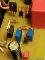
Last days I made a modification on my JLH, I added another CCS for Tr3 made from one DN2540.
The bootstrap amplifier sounded great, I used Black Gate 470uF / 35V, but the other CCS added a bit more dynamics and detail.
I tried a little different transistors for Tr3, but now with the other CCS I have to do it all again.
Before CCS I tried, KSC3503,2SC2229,2SC2383,2SC2705, BC337, BD139 and my favorite 2SD438. The best sound for me have
1.2SD438
2.KSC3503 / 2SC2229
3.BC337-40
2SC2383 and 2SC2705 was a disappointment.
With CCS I have been testing 2SC1941,2SC3593, KSC3503 and today 2SC3116. 2SC1941 was a real invention, I did not have such a sound with bootstrap before. The KSC3503 is no longer brilliant as the 400MHz Sanyo 2SC3593. The 2SC3116 I listen to this afternoon is also a good choice, but I need to give it a few more hours.
The amplifier was stable without any compensation to all the above transistors.
For the next test I still have 2SC2690,2SC3421,2SC3423
It also seems to me that now has a great deal of hfe from Tr3, the higher hfe has a better sound.
Attachments
Last edited:
- Home
- Amplifiers
- Solid State
- JLH 10 Watt class A amplifier