You could use the JLH as Follower (input base Tr 2) or as "single gain" (input base Tr 1)
I prophesy, it will sound much much cleaner than the original JLH;-! The Follower will sound best;-!!! Pure stressless - compared with the amp/s;-)))
Bootstrap remove;-!!!
I prophesy, it will sound much much cleaner than the original JLH;-! The Follower will sound best;-!!! Pure stressless - compared with the amp/s;-)))
Bootstrap remove;-!!!
I know. I minimized the circuit and used it as a line buffer. Would imagine it works for headphones and speakers as well.
You could use the JLH as Follower (input base Tr 2) or as "single gain" (input base Tr 1)
I prophesy, it will sound much much cleaner than the original JLH;-! The Follower will sound best;-!!! Pure stressless - compared with the amp/s;-)))
Bootstrap remove;-!!!
Hi cumbb,
Can you show your schematic? Thank you.
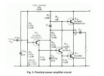
The original JLH.
"This" follower sounds better than others! Reason, less complex "drive-supply.circuit", bipolar-transes, no power-resistor. A dream. Amp too;-)
Do not forget the coupling-caps;-)
Set three inputs at your cases;-)
"This" follower sounds better than others! Reason, less complex "drive-supply.circuit", bipolar-transes, no power-resistor. A dream. Amp too;-)
Do not forget the coupling-caps;-)
Set three inputs at your cases;-)
Attachments
Lets say JLH did listen to the sonic problems of time constants. I guess the best results will be close to his choices. However, you can listen for yourself. If you buy new speakers always try a retune.
The JLH as a follower could work. It would have very low distortion. What might be interesting is to give the amp a gain close to two. That is 2K7 as usual, 2K2 to replace 220R and 22uF 100V polyester to replace 220uF. We now have the option of feeding music into the 22uF which could just about get to full output from a good op amp. Say 24Vpk to pk = 8.4Vrms x 2700/2200 = 11.34 Vrms. That's 16 watts 8 ohms. The output signal inverts so either build an inverting buffer to the volume control or swap speaker plus and minus. It makes a small difference to be in correct phase. The inverting buffer is nice.
My brother thought the best reason for saying an inverting amplifier is best is the gain formula is just -G=A/B which shows it reduces to zero at some point. When the power amplifer the speaker signal and music signal meet face to face and not down a telephone of the base emitter junction ( or two of them in most amps ). Personally I find the difference hard to hear when a simple amplifer. All the same it seems likely it will be heard if every bit of tuning is done. An inverting amplifier can be more stable if something stupid is done. I like DIN or XLR plugs to enhance that sort of safety.
Bryan Amplifiers had a cartoon man and a bucket of water " I should have bought a Bryan Amplifier ". Bryan used the capacitor coupled Tobey and Dinsdale 1961 design. Said to be a very goood example. They hard sold capacitor coupling as a prime reason to buy. The T&D preamp designs are very interesting.
The standard non inverting input would have a gain of 1+ ( 2700/2000) = 2.23. That needs 5V rms. The advantage here is the volume control gets both gain and a buffer. It is most likely not the best idea for this style of amplifier. All the same a nice idea if wanting a complete collection of options. I suspect it would need a VAS capacitor ( collector to base on the driver NPN ). 68pF might be where to start. Fit a Zoble circuit of 100nF 4R7 3watt. If the resistor gets hot borrow a scope. I think it will need 33 pF regardless. I tried different ways to do that. The boring VAS cap was easiest.
Below is a headphome amplifier that could do a good job as a volume control buffer. It should do 8Vrms into 2K. The green resistor is an SE class A option for the op amp. As BC337-40 is high gain the op amp will be in PP class A. I tried the dreaded LM358 and saw no crossover distortion just as the makers say into high resistance. It should work with any op amp you like and drive headphones. You would have a input coupling capacitor which I haven't drawn. I did this years ago. This idea could be scaled up to be a power amplifer. Set the gain as suits best. Input resistor can be changed from 10K to a higher value to suit the volume control. If 20 K log I would guess 33K input about right ( 22K min ). Hiss is the problem. Hiss is better than a squashed sound. My instinct is less is more and this gets to be slightly more complicated than I like.
In your headphone amp, best way to place the class-A pull resistor would be between B-E of the upper BJT which makes it a quasi CCS (been there). The way you have it now would on the other hand make it a "Class-RXD", haha - isn't the Class XD a fancy and super smart voltage-controlled CCS? Ohm's law dictates a simple resistor is a simple and stupid voltage dependant current sink.
So Class-RDX it is.
So Class-RDX it is.
I can see plenty of ways to make a better version. For a start use 2 x 1N4148 both sides. When the CCS was replaced by a resistor it was great. The green resistor can be to -ve or +ve. 10K would be fine. The data is not bad.
"Class RDX" works wonder with opamps. If psu quality permits, it's easy to sneak 0805 pull resistors into existing circuits (speaking of existing tru-hole designs).
But realistically with opamp+follower circuits, I always try to maintain hygiene and include a couple-ten pF cap between opamp output and -input, corner set at couple 100kHz to keep the transistor out of the nfb at higher frequencies.
But realistically with opamp+follower circuits, I always try to maintain hygiene and include a couple-ten pF cap between opamp output and -input, corner set at couple 100kHz to keep the transistor out of the nfb at higher frequencies.
I think, John would be the last one, who would forbid us, to alter "his" circuits, schemata;-) He would be one of the first changer;-)
A BALANCED JLH would be final;-!!!
A JLH is simple enough to get all advantages of balancing - I know about some people who x-stages-complementary-pp-amps balance and do use separate psu-rails, x-psus, x-rails for this - Am I Soooo Inexperienced (scratching my head)-?!?!
I have read in here about op-amps and line-buffers and so on. Could you construct Tr 4 as differential-amp?
Or which points in the JLH circuit we could use for balancing;-?
But use only ONE psu for all;-!!!!!!
After that remove, throw in the bin, all your pre-, line-, op-, x-amps, all your topsy-turvy-junk;-)
mj802g
I am building another high power JLH amp but with separate psu using capacitance multipliers.
My mk1 version uses 4xMj15003G with an unregulated psu (18-0-18ac 225va + 69000uf per rail per channel) and there is a little hum audible.
Has anyone used MJ802Gs instead of MJ15003G? RS have them in stock but they seem to have somewhat lower hfe (~80) albeit much higher than the 2N3055?
I was fortunate to win a massive 100mm fan cooled heatsink assembly pre drilled for 24xTO3. Its made up of 8 heatsinks insulated from each other and the frame with Tufnol spacers so I plan on not using TO3 insulators . There are 4 large heatsinks for the amps, and 4 smaller ones for the capacitance multipliers.)
When you use cinch-plugs, do use one channel only for ground. I do use the right one for ground;-)

Some years ago I built this. At the time I didn't think it very good. Looking back it was. The bias as shown was very sensetive to the red resistors. I show two as it might be a way of centering the ouput. I also show loop feedback to either the op amp or the output stage. The measurements were indentical which shows the local feedback in the output pairs really works. Even at 64 kHz this was true. No reason it has to be an op amp driving it. It could be diven by an EL84 or ECC82 ( 12BH7A ). Capacitor coupled the EL84 output would be the easier way. In triode EL84 has reasonable voltage gain, about 12 if I remember.
If you change the 0R1 emitter resistors that is another way to change bias. The beauty of this way of bias setting is the 1N4007( 1,2,4 etc ) mostly tracks the output transistors. I mounted the BD135/6 on the big devices and then fixed a diode to each group using epoxy glue. I would imagine other diodes might give better adjustment range. 1N4148 might. The 10K can be changed also. This was beginers luck. It worked first time.
The small advantage of this idea is less bias will do the job just fine. When the signal gets high enough class AB steps in, the JLH can't do this. Most people will hear this amplifer as being pure class A. It is said 1 watt is enough. Here it is more. The AB power into 4 ohms might be 30 watts. I would be more if the op amp could do it.
I thought it would be fun to show it. It should be less fussy than some designs. PSU to the op amp can be just it's own rectifier and capacitors. Very cheap class A. All this design is, is the absolutely standard op amp booster made class A. The feedback pair output devices mimic very high gain single transistors. This means the op amp has very little work to do. The very critical biasing shows how theory and reality are very close. Basically this 1956 idea functions as a super linear three terminal device of 0.6V bias.
Hi Batteryman,
I used the MJ802s when I repaired my Bedini 25.25 some years back due to their availability, and what a difference. The bass was better defined, mids so much cleaner and the highs crystal clear. I am in the process (very slowly) of building two high power JLH mono-blocks (I have stacked Quad ESLs) in which I will be using a capacitance multiplier as per the Class A Amplifier site. FWIW,mMy power transformer for each amp is a 400VA toroidal with 2 x 20V secondary windings.
All the best with yours.
Kevin
Last edited:
I'm jealous. It's said if two pieces of MDF are added to single ESL57's it can fake the advantages of pairs as the baffle is made larger. The Quads have very good bass, a little more is nice. Someone asked me where the subwoofer was when I had a pair. No subwoofer.
Gaborbela, it's actually cheaper to get the MJ802 directly from RS Components, Mouser or Digikey. They're under just $4 a pop in the USA and in the UK £3.
Hi Nigel, I must admit that I was very lucky to get the stacked ESLs. A very good friend virtually gave them to me. I paid roughly £300 for the stacked set some 22 years back. I've never been sorry. Been driving them with the Bedini 25.25 since. The Bedini does need to be rebuilt though - 20 years of constant use has taken its toll. Had to replace the transistors (2N3055s with MJ802s and input BJTs with BC550C/560c) after a lightning strike, and various capacitors over the years. Tracks on the PCB are lifting off in places from the continuous heat. Will strip one of the boards of all components and then scan it.
Will tackle that sometime later on though. I first want to get the high power JLH built, so that I can still listen to my music.
Kevin
P.S. Oh, and my friend gave me all his spare panels - 3 off mid/treble panels and 5 bass panels.
Last edited:
@gaborbela - the RCA 40411 might have similar ratings to MJ802 but not the same performance. 40411 was a slow hometaxial device which might have managed 200kHz ft (800kHz typical) but the MJ802 is an epi device and was/is spec'd at 2MHz. Don't believe any hometaxial devices are made any more (not by RCA anyway - they disappeared years ago), but the MJ802 is still around, I think.
Hi Batteryman,
I used the MJ802s when I repaired my Bedini 25.25 some years back due to their availability, and what a difference. The bass was better defined, mids so much cleaner and the highs crystal clear. I am in the process (very slowly) of building two high power JLH mono-blocks (I have stacked Quad ESLs) in which I will be using a capacitance multiplier as per the Class A Amplifier site. FWIW,mMy power transformer for each amp is a 400VA toroidal with 2 x 20V secondary windings.
All the best with yours.
Kevin
I bought a used pair of ESL63s some years ago and this was a revelation even though they needed an overhaul.
I now have Martin Logan Aeon hybrids which have a much smaller footprint, being tall (1.8m) but narrow and are an equally difficult load but the bass is much better than the ESL63s.
I experimented with my MK1 High Power JLH using a 0-40v x2 10amp lab switch mode psu to set the current but perhaps not surprisingly, when auditioning the amp, the sound quality was not pleasant. (I suspect the psu transient response was very poor).
I slightly prefer 63's over 57's is the brown grille is removed. The guy who showed me this had a 5 year old daughter who played near them! He used a Marantz Model 9 with capacitor upgrades.
My 6 watt SE valve amp using EL34 made the 63's go loud enough for me. The stereo imaging in a normal sized room when 63's is the advantage. In standard form 63's sound dull. If you have a long room try them half way up so the figure of 8 output can show. If the amplifier has poor damping factor the 63's will work very well, my EL34 amp for example. This makes low loop feedback amps usable. For what it's worth I like EL34 more than typical 300B's. KT88 less than EL34. Never tried GU50's.
My 6 watt SE valve amp using EL34 made the 63's go loud enough for me. The stereo imaging in a normal sized room when 63's is the advantage. In standard form 63's sound dull. If you have a long room try them half way up so the figure of 8 output can show. If the amplifier has poor damping factor the 63's will work very well, my EL34 amp for example. This makes low loop feedback amps usable. For what it's worth I like EL34 more than typical 300B's. KT88 less than EL34. Never tried GU50's.
I would imagine that mounting BD's on output bjt's would in fact make a positive thermal feedback which can't be totally nulled out or compensated for with diodes....
I mounted the BD135/6 on the big devices and then fixed a diode to each group using epoxy glue.
...
With some of my own (low power, mind you!! less than 5w) designs I was absolutelly obsessed with thermal decoupling of drivers and output, pcb-layout wise. And getting diodes (pedestrian 4001's) each on output devices' heatsink (outputs each on their separate heatsinks). And even then I was getting more heat/bias rise than I was happy with.
I was recently recapping one such "invention" of mine and was again reminded of how hot it got. Perhaps mains are running "hotter" these days that they used to. (unregulated psu).
- Home
- Amplifiers
- Solid State
- JLH 10 Watt class A amplifier