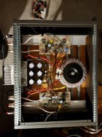
I will do one better if I can and build one. I need to repair my oscillator so as to do measurements. If possible I will simplify the DC point. I will use capacitor coupling as it simplifies the power supply ( PSU ).
Looking at the design in general TR3 2N697 seems to be critical. On paper a BD139 or it's TO92 BC639 cousin look to have slightly less gain. I would imagine BC337-40 better ( Vce 45 V , suits JLH 36V recommendation ). I would imagine 22 pF added collector to base to mimic the original wise. I suspect if test gear available this could be removed. I also suspect the modification would allow any low gain TR1 to be used. I have to guess BC337 to be a higher current device as data is limited. I am away from home where I have an old Towers data book which will tell me more.
In a class AB amp we couldn't look to a simple modification like this. A 2N3055 has a current gain of 5 into a difficult load ( as Gogny 1967 amp ). If the output current was 8V/2R we are near to 1 amp into the 2N3055 base. The 3055 will take more if asked, >3 is implied in specs. In a true class A amp which can not go into AB this will not happen. That's why I tried MOS FET's ( Exicon 10N/P20 or BUZ900/905 ) for my A +AB JLH tribute idea. Audio FET's do not work as a bipolar device so do not kill the driver stage.. Hence my square wave tests to see reality matched to theory. 10 kHz was fine and 30 kHz OK. We only really need 5 kHz. No CD player can do a 1.2 kHz square wave if using the 19 th term of Fourier series as a realistic end point ( infinity in theory, 1/19 f19 is usefully close ).
It should be that BC337-40 with 2N3055 would work well. I imagine IM distortion to be lower than most JLH built. TTC5200 ( 2SC5200 ) could be used if as much as 1200nF added to the base collector terminals to match a real 1969 2N3055H. Some 3055 measure Cob of 1400 pF and clone types 500 pF. The TTC 5200 more like 150 pF. Why throw away HF ability? Simple, when class A there is no switching. The distortion we get can not be heard and is mostly second harmonic if > 7 kHz. Unlike class AB the results of switching as TID are not heard. Thus all we need is gain. The TTC5200 has on paper 5 times the current gain. That makes a BC337-40 + TTC5200 20 times easier to drive. Reality makes it less ( added capacitance ). What one should hear is greater transparency in the 500 Hz to 3 kHz range, above 3 kHz the test gear needs to be used to take away added pF. Remember this. A 1000 +220 pF COG/NPO ceramic is a much nicer capacitance than the Cob of a 2N3055. So making a 30MHz device slow to perhaps 1MHz is still best of type. If the R3 was made 100R and these modifications I suspect 0.01% THD not impossible. R3C4 can be used as an input. A preamp to drive headphones could do that. Remember to invert the speakers if you do. In theory that way sounds best as the negative feedback is a direct sum of output and input and not via the base input of TR4 ( BC327-40 or BC560C beware of fakes of the latter ). Others say the gain formula ends at 0 being the real reason, the base side at 1 or a plateau. It will sound awful if the preamp can not drive 220 or 100R.
Output Transistors
This is the corect way to solder the 2SA970 right Prasi?
Yes. great, you already seem to have progressed well with stuffing.
Regards
Prasi
I would use TO-220 package only.
I would build the original circuit - 1 psu!
Maybe, I would not use the input transe.
For the rest I would use 3 times the same transes. ALL the same! expl: BDT93
I would use an active psu.
I would use not big cans, but some little ones. Set as "ONE circuit".
And, certainly, I would not use a board;-)
When home I will see if I can find Cob for original transistors MJ480 that seems to match modern 2N3055 epitaxial types with Ft to 4MHz. My guess is TTC5200 + 330 pF about where this idea will go. The idea of using LM317 ( CCS to replace TR2 ) for the moment is not workable as one can not signal modulate it as easily as the JLH. One can modulate the adjust pin so maybe.
I will do one better if I can and build one. I need to repair my oscillator so as to do measurements. If possible I will simplify the DC point. I will use capacitor coupling as it simplifies the power supply ( PSU ).
Looking at the design in general TR3 2N697 seems to be critical. On paper a BD139 or it's TO92 BC639 cousin look to have slightly less gain. I would imagine BC337-40 better ( Vce 45 V , suits JLH 36V recommendation ). I would imagine 22 pF added collector to base to mimic the original wise. I suspect if test gear available this could be removed. I also suspect the modification would allow any low gain TR1 to be used. I have to guess BC337 to be a higher current device as data is limited. I am away from home where I have an old Towers data book which will tell me more.
In a class AB amp we couldn't look to a simple modification like this. A 2N3055 has a current gain of 5 into a difficult load ( as Gogny 1967 amp ). If the output current was 8V/2R we are near to 1 amp into the 2N3055 base. The 3055 will take more if asked, >3 is implied in specs. In a true class A amp which can not go into AB this will not happen. That's why I tried MOS FET's ( Exicon 10N/P20 or BUZ900/905 ) for my A +AB JLH tribute idea. Audio FET's do not work as a bipolar device so do not kill the driver stage.. Hence my square wave tests to see reality matched to theory. 10 kHz was fine and 30 kHz OK. We only really need 5 kHz. No CD player can do a 1.2 kHz square wave if using the 19 th term of Fourier series as a realistic end point ( infinity in theory, 1/19 f19 is usefully close ).
It should be that BC337-40 with 2N3055 would work well. I imagine IM distortion to be lower than most JLH built. TTC5200 ( 2SC5200 ) could be used if as much as 1200nF added to the base collector terminals to match a real 1969 2N3055H. Some 3055 measure Cob of 1400 pF and clone types 500 pF. The TTC 5200 more like 150 pF. Why throw away HF ability? Simple, when class A there is no switching. The distortion we get can not be heard and is mostly second harmonic if > 7 kHz. Unlike class AB the results of switching as TID are not heard. Thus all we need is gain. The TTC5200 has on paper 5 times the current gain. That makes a BC337-40 + TTC5200 20 times easier to drive. Reality makes it less ( added capacitance ). What one should hear is greater transparency in the 500 Hz to 3 kHz range, above 3 kHz the test gear needs to be used to take away added pF. Remember this. A 1000 +220 pF COG/NPO ceramic is a much nicer capacitance than the Cob of a 2N3055. So making a 30MHz device slow to perhaps 1MHz is still best of type. If the R3 was made 100R and these modifications I suspect 0.01% THD not impossible. R3C4 can be used as an input. A preamp to drive headphones could do that. Remember to invert the speakers if you do. In theory that way sounds best as the negative feedback is a direct sum of output and input and not via the base input of TR4 ( BC327-40 or BC560C beware of fakes of the latter ). Others say the gain formula ends at 0 being the real reason, the base side at 1 or a plateau. It will sound awful if the preamp can not drive 220 or 100R.
Output Transistors
I can not find the data of the BDX50 but I think it is a good candidate.
0.800Mhz and weak FT but very hard to find today.
military transistor, there is no counterfeit.
I use it on a jlh for years with pleasure
Hi, but if I put the Iq to 2A or more is it possible to have more bass or it is only a danger to kill samething without good improvment? Thks.
Mleod
Mleod
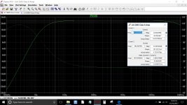
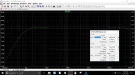
Iq will not affect the frequency response. In the circuit you posted earlier, C1 and C3 are the only ones to affect response.
As it stands with 2.2uF and 470uF the response is -1db down at 4.6Hz. Make those caps 4.7uF and 1000uF and you get to 2.1Hz approximately.
As it stands with 2.2uF and 470uF the response is -1db down at 4.6Hz. Make those caps 4.7uF and 1000uF and you get to 2.1Hz approximately.
Attachments
Hi Mooly,
thanks for the very precise and detailed information, it will mean that I will try to work on those 2 capacitors to get an improvement.
However, I would also be content with the theoretical results you expressed if it were not that in practice what results in my case does not satisfy me.
Thanks anyway, ensuring that my next intervention will be aimed at C1 and C3.
Greetings all
Mleod
Would it be possible for you to post your schema with values used and pics?
What is your source? Do we require a buffer after volume pot?
Regards
Prasi
What is your source? Do we require a buffer after volume pot?
Regards
Prasi
Hi Nigel thank you for the attachment you posted (#4014); big help.
Just a question; can you tell us more about the relatively simple direct couple MosFet Power Amp on page 124 pls.
Cheers Jonathan
Just a question; can you tell us more about the relatively simple direct couple MosFet Power Amp on page 124 pls.
Cheers Jonathan
i don't understand your problem with your amp.Hi Mooly,
thanks for the very precise and detailed information, it will mean that I will try to work on those 2 capacitors to get an improvement.
However, I would also be content with the theoretical results you expressed if it were not that in practice what results in my case does not satisfy me.
Thanks anyway, ensuring that my next intervention will be aimed at C1 and C3.
Greetings all
Mleod
i never hear jlh amp with no bass.
even the 2005 Chinese jlh which is for me the worst has deep bass.
one thing I would like to know, are you sure of the origin of your transistors,
because ,today is 80% of fake on the market in old references of transistors...
Some comments about Nigel's post #4022 -
first, I'm not sure what design we are discussing, so could we have a circuit diagram please?
As regards the transistors, I would have some concern about a BC337 simply because of the power dissipation. Those old TO-5 can transistors were quite good in that respect, and I would tend to recommend the BD139 type now. That too can be obtained from some suppliers in the higher gain group -40, as I agree that in the JLH as much gain as possible is needed.
In comparing simulations of 2N3055H, the old hometaxial RCA device, with a modern epi 2N3055 and 2SC5200, it is clear that the higher frequency devices give the best square wave, though I had to make a model for the 2N3055H because most models "out there" do not give the right ft. That has a knock-on (or maybe knock-back) effect on the input transistors which can cut off just as easily as in a Class AB amplifier, hence the 2N3055H being the slowest has the worst susceptibility to TID or SID.
It is not worth loading the high ft devices with additional capacitance unnecessarily, but it is worth noting the high input capacitances which need quite a high base drive. Therefore, despite having made a 2sC5200 JLH (which sounds excellent) but needed a 33pF stabilisation capacitor across the feedback resistor, it appears that the earlier epi devices might actually be optimum in this design - like the MJ481. Luckily I found the old data sheet and it has a maximum output capacitance of only 200pF, but that probably reflects a rather small chip which can only handle 4A. But with low capacitances in general, driving the device should be straightforward.
As for a 2N3055 "only having a gain of 5" I'm not sure why anyone would push the output current in this device to such an extent that the gain has almost gone. Its spec. is 20 at 4A, and I tend to limit the current in circuits using a 2N3055 to 6A where the lowest gain is taken to be 13.
Hi Nigel thank you for the attachment you posted (#4014); big help.
Just a question; can you tell us more about the relatively simple direct couple MosFet Power Amp on page 124 pls.
Cheers Jonathan
Sometimes I read something and see a new idea. Douglas Self says the better class A could be the overbiased AB as long as it is biased to have at least enough current to do 20 watts in class A. Giving it some thought 5 watts seems enough as long as we might look to 20 watts AB 6 ohms. The great problem with the Self idea is the amplifier is almost certain to be unreliable if keeping things simple. FET's for all of their problems can offer reliability with simple resistor biasing. The heat sink should be at no more than 50C at idle ( 0.7A ). I might add this to the Self class A/G design one day.
The input and VAS are typical of 1960's amplifiers at slightly higher current. A single input transistor produces a nice distortion curve where the harmonics are progressively lower in level where second is highest ( unlike many modern amps ). Purple VAS emitter resistor can be anything you like >0R ,<100R. The VAS current can be adjusted by ear also. 5.6 mA to drive the FET's seems about right ( 2 to 8 mA ). As the outputs are source followers the Cgs ( x 2 of ) circa 500 pF is not the question as it is bootstrapped to the speaker, The important Cgd comes in which could be 300 pF. As you notice 50 kHz was not a problem so I discount any FET's have too much capacitance theories. Notice how the 47R ( 16R also was liked ) to the VAS emitter actually reduces the 50 kHz distortion. I suspect it sweet-spots the loop gain. Thus I do not say local feedback although in some senses it is. All things being equal it shouldn't make a difference. It does which is intriguing.
The feedback from FET's sources to VAS CB is a nice free lunch ( looks like 2 pole compensation ). I was surprised it worked without trouble. Interesting to note a complimentary feedback pair of very fast devices looked identical to the FET's without this feedback. The feedback bipolar pair only needed 2 x 1N4007 and a single 4R7 resistor to bias them to 0.7A. That's far too critical ( 8mA VAS current ). I used conventional Vbe bias which was fine. I felt at that point the JLH a clear winner. The FET's to bring in the simplicity I admire.
One reason I did this design was to test the idea that old germanium output stages might be replaced with a pair of FET's ( replace quasi complimentary 3 PNP and 1 NPN ), The biasing might be 50 mA if so, 20 mA if needs must, 100 mA ideal. The 470R bias I show to get 0.7A is ball park for that batch of FET's only in class A+AB. The funny spot frequencies where to be 10 kHz and 20 kHz. They were the nearer values I had to hand for the oscillator. I didn't bother to tweak it.
John. Gain of 5 for 2N3055 was worse case. I suspect the modern TTC(2SC)5200 could be 5 times better. As far as I know the 2N3055 sold today are not really the device of 1969. I suspect MJ15015 if fall out spec is a 3055. The point I was making was that if we took a TTC5200 and retained it's gain whilst reducing Ft we might have best of all worlds.
As to BC 337-40 being OK it should be as the original device looked no better ( when home I will check Towers International Transistor Selector to get better data ). The later T05 could dissipate more heat ( not unlike BD139 ).
As to BC 337-40 being OK it should be as the original device looked no better ( when home I will check Towers International Transistor Selector to get better data ). The later T05 could dissipate more heat ( not unlike BD139 ).
Greetings to everyone!
PRASI
If the post # 4031 is addressed to me, please read the # 4003, bearing in mind that the components are those of the scheme for the same values, I consider them good quality. Keep in mind that in terms of sources and system in general, interchanging the amp with a Hiraga class A the difference is important in all combinations, in my opinion. If I am not the recipient please ignore this post, I will work on C1 and C3. Thank you.
Greetings
Mleod
Sometimes I read something and see a new idea. Douglas Self says the better class A could be the overbiased AB as long as it is biased to have at least enough current to do 20 watts in class A. Giving it some thought 5 watts seems enough as long as we might look to 20 watts AB 6 ohms. The great problem with the Self idea is the amplifier is almost certain to be unreliable if keeping things simple. FET's for all of their problems can offer reliability with simple resistor biasing. The heat sink should be at no more than 50C at idle ( 0.7A ). I might add this to the Self class A/G design one day.
The input and VAS are typical of 1960's amplifiers at slightly higher current. A single input transistor produces a nice distortion curve where the harmonics are progressively lower in level where second is highest ( unlike many modern amps ). Purple VAS emitter resistor can be anything you like >0R ,<100R. The VAS current can be adjusted by ear also. 5.6 mA to drive the FET's seems about right ( 2 to 8 mA ). As the outputs are source followers the Cgs ( x 2 of ) circa 500 pF is not the question as it is bootstrapped to the speaker, The important Cgd comes in which could be 300 pF. As you notice 50 kHz was not a problem so I discount any FET's have too much capacitance theories. Notice how the 47R ( 16R also was liked ) to the VAS emitter actually reduces the 50 kHz distortion. I suspect it sweet-spots the loop gain. Thus I do not say local feedback although in some senses it is. All things being equal it shouldn't make a difference. It does which is intriguing.
The feedback from FET's sources to VAS CB is a nice free lunch ( looks like 2 pole compensation ). I was surprised it worked without trouble. Interesting to note a complimentary feedback pair of very fast devices looked identical to the FET's without this feedback. The feedback bipolar pair only needed 2 x 1N4007 and a single 4R7 resistor to bias them to 0.7A. That's far too critical ( 8mA VAS current ). I used conventional Vbe bias which was fine. I felt at that point the JLH a clear winner. The FET's to bring in the simplicity I admire.
One reason I did this design was to test the idea that old germanium output stages might be replaced with a pair of FET's ( replace quasi complimentary 3 PNP and 1 NPN ), The biasing might be 50 mA if so, 20 mA if needs must, 100 mA ideal. The 470R bias I show to get 0.7A is ball park for that batch of FET's only in class A+AB. The funny spot frequencies where to be 10 kHz and 20 kHz. They were the nearer values I had to hand for the oscillator. I didn't bother to tweak it.
Dear nigel,
Which is the actual circuit to which the above comments refer to ? Can you kindly post it here ?
--gannaji.
Fascinating how periodically there is a resurgence in interest in the J.L-H. 10 Watt Amp.Not surprising as he was a very thoughtful designer. I have found that the simpler the set up the better. I have a CD compatible Blu-Ray player,whose output is 2.5 V RMS.I drove my 2 X 12 W GEM derived Class A monoblocks directly via 2 pots (Bal and Vol ),the result was stunning.Even the Freeview radio channels sounded better than my DAB tuner.Some time ago I built a pair of J.L-H s using 2SC5200 in the op.stage,full report in a previous post. Engineering is always a compromise, making an improvement one area can sometimes be at the expense of another.A sort of "Whack-a mole" situation!
Greetings to everyone!
PRASI
If the post # 4031 is addressed to me, please read the # 4003, bearing in mind that the components are those of the scheme for the same values, I consider them good quality. Keep in mind that in terms of sources and system in general, interchanging the amp with a Hiraga class A the difference is important in all combinations, in my opinion. If I am not the recipient please ignore this post, I will work on C1 and C3. Thank you.
Greetings
Mleod
ok, sorry I had missed the post.
what I feel is, if this amp has such following everywhere, you may need to investigate your build closely to detect issues.
I fully agree with huggygood regarding this amp, gut feeling!.
regards
Prasi
Use little frame-sizes for coupling-caps. The bigger the frame (not the capacitance), the bigger the image-differences of all frequencies: the bass seems behind, fluffy, diffus;-)
Big MKPs and other sound horrible - un-audible;-)
One reason, my mind, why the JLH sounds so good: bipolar-transes. Everytime after a change MosFet - Bipolar (same amp, same circuit) the sound is minimal more cleaner, finer, naturally, fluid.
My experience;-)
Big MKPs and other sound horrible - un-audible;-)
One reason, my mind, why the JLH sounds so good: bipolar-transes. Everytime after a change MosFet - Bipolar (same amp, same circuit) the sound is minimal more cleaner, finer, naturally, fluid.
My experience;-)
- Home
- Amplifiers
- Solid State
- JLH 10 Watt class A amplifier