Well, there is no smoke without fire.... might try it some day 🙂
Maybe, for now I think that using a good bipolar is preferred.
Cool statement: "With VGT, the SNR is constant, regardless of volume setting."
How did he do it ? I have been searching for a variable gain stage forever now.....
The metal case is also a piece of kit 🙂
I think they make it transimpedance, like in the Paradise. Instead of the RIAA components you could use a resistor to set the gain ( e.g. various resistors ).
I am not sure though that we then get the same distortion and frequency response on all levels.
We have discussed to make a modern DIY preamp but the project was cancelled due to the enormous time it takes. Do not even talk about the nightmare of group buys.
On another thread in Germany ( Frickelfest Forum ) we are doing a " Digital " phono stage, that is a linear amp with MC or MM sensitivity, then a volume control we will eventually do with the Muses chip. Then an AD converter and the RIAA implemented in DSP then DA converter. Maybe that volume control is usable for a line stage too.
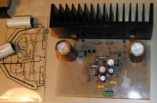
it is working smoothly.... no cap at the input but no offset in or out.
It does amplify..... I would apreciate some sugestions about measurements I should do before connecting it to the speakers.
It does amplify..... I would apreciate some sugestions about measurements I should do before connecting it to the speakers.
You should use a dummy load, say 4 to 8 Ohm and put a squarewave in ( 1kHz, 10kHz ) and watch on the scope if there is any overshot. You can then try to put 1uF in parallel.
The square then has ringing but still the amp should not oscillate.
The miller cap in this amp is quite high so the square should be stable.
You can also check the idle.
The square then has ringing but still the amp should not oscillate.
The miller cap in this amp is quite high so the square should be stable.
You can also check the idle.
How can I check the idle ? On the dummy load ?
already heard it's sound in my bench setup..... quite good.... Only one small issue, The heat sinks are not grounded and when I touch them with my hand, sound volume diminishes sensibly... what does this mean ?
already heard it's sound in my bench setup..... quite good.... Only one small issue, The heat sinks are not grounded and when I touch them with my hand, sound volume diminishes sensibly... what does this mean ?
You can check the idle over the emitter resistors R15, R16.
You measure the voltage over one or both of them. Idle is then U/R = I.
U is the voltgae you measure, R is 0.22 Ohm or 0.44 Ohm.
Does the fane of the output transistors make contact to the heat sink ?
You measure the voltage over one or both of them. Idle is then U/R = I.
U is the voltgae you measure, R is 0.22 Ohm or 0.44 Ohm.
Does the fane of the output transistors make contact to the heat sink ?
Idle settles at 12mA after 5 min (It goes down when heat goes up) must stabilize when properly enclosed.
The output transistors are isolated..... heatsink is not connected to anything. Anyway, today this dimming effect is not aparent..... maybe it was due to the presence of dmm probes.
The output transistors are isolated..... heatsink is not connected to anything. Anyway, today this dimming effect is not aparent..... maybe it was due to the presence of dmm probes.
I would connect the heat sinks to ground then.
Idle is fine. You can always make it higher with more transdiodes in series in the bias string.
Idle is fine. You can always make it higher with more transdiodes in series in the bias string.
Actually that has to be simulated. I am not sure at the moment if the 300 Ohm base stoppers matter here.
My original circuit had another bias spreader. I think it was an amplified diode so i could dial it in with a trimmer.
The Muses volume control chip is a ladder attenuator on the chip from NJR that is reported to sound very good because it does not have an opamp in it. Maxim and Dallas Semiconductor do something similar.
Here we go :
MUSES72320,MUSES72320V (18V Operation 2-Channel Electronic Volume) | MUSES Official Website
They also make Muses Opamps with a special clean process but i have not heard them.
I use NJR chips here and there and they are competitive with the american makers in certain regards. They are very chepp too, not the Muses, that is.
Have you tested the MUSES72320 yourself, Joachim ?
Any impressions ?
Also a belated Happy New Year.
BTW I sent you a email a few days ago. Did you receive ?
BR,
Patrick
Any impressions ?
Also a belated Happy New Year.
BTW I sent you a email a few days ago. Did you receive ?
BR,
Patrick
Here we go :
MUSES72320,MUSES72320V (18V Operation 2-Channel Electronic Volume) | MUSES Official Website
They also make Muses Opamps with a special clean process but i have not heard them.
I use NJR chips here and there and they are competitive with the american makers in certain regards. They are very chepp too, not the Muses, that is.
Is it similar to PGA2311 from BB ?
if I place more two transdiodes, what would be the expected bias current ?
If the current temperature coefficient is negative (e.g. the bias current goes down when temperature goes up) then I would not add a second diode. Use a (to start with) 100 ohm potentiometer and see what happens (if not to much use a 500 ohm one).
- Status
- Not open for further replies.
- Home
- Source & Line
- Analogue Source
- JG´s Nobrainer and Nobrainer Discrete