PF5102 I bought 2500 for a dime each.
Hello All,
PF5102
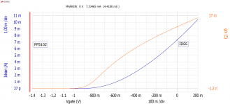
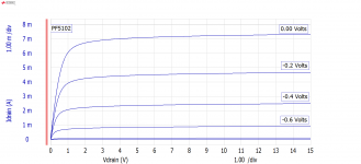
I bought 2500 for a dime each. I tested a random sample; the first ten that fell out of the bag. It looks like the distribution of values does not spread all that wide. Finding matching pairs does not look too difficult.
Or as Papa does, using a source resistor will match lots of JFET’s
See the attached typical plots.
IDSS mA gm mS
10.145 15.75
7.6147 14.32
11.290 15.72
5.4625 12.99
7.2822 14.20
8.2458 14.79
10.352 15.25
10.010 15.23
6.9013 13.90
6.1535 13.55
J113
A similar stash of J113’s had an average IDSS only a couple mA higher.
Thanks DT
Hello All,
PF5102
I bought 2500 for a dime each. I tested a random sample; the first ten that fell out of the bag. It looks like the distribution of values does not spread all that wide. Finding matching pairs does not look too difficult.
Or as Papa does, using a source resistor will match lots of JFET’s
See the attached typical plots.
IDSS mA gm mS
10.145 15.75
7.6147 14.32
11.290 15.72
5.4625 12.99
7.2822 14.20
8.2458 14.79
10.352 15.25
10.010 15.23
6.9013 13.90
6.1535 13.55
J113
A similar stash of J113’s had an average IDSS only a couple mA higher.
Thanks DT
Attachments
Hello i do not look for a 2sk170 equivalent, i am looking for a jfet, in any package, that is currently available, cheap (not like linear system lsk) that is low noise.
The lowest noise in production jfet ?
A new bf862 style alternative.
I do not care about sound, only low noise.
Thank you.
The lowest noise in production jfet ?
A new bf862 style alternative.
I do not care about sound, only low noise.
Thank you.
Cheap and low noise ?
Use multiple 2SK209GR or 2SK209Y in parallel.
NJFETs for Source Follower Applications
Patrick
Use multiple 2SK209GR or 2SK209Y in parallel.
NJFETs for Source Follower Applications
Patrick
Maybe not as low noise as the 2SK170, but also lower capacity. You may parallel them to achieve lower noise. In that case, the GR variety comes in handy:
2SK209-GR(TE85L,F) Toshiba | Mouser Schweiz
2SK209-GR(TE85L,F) Toshiba | Mouser Schweiz
Thank you guys, what is the difference between the GR and the Y?
Also If you have the lowest noise possible configuration circuit for an input buffer (hi impedance) please tell me ?
Also If you have the lowest noise possible configuration circuit for an input buffer (hi impedance) please tell me ?
GR and Y are different Idss classes, its on the Datasheet on Page 1. Its the max current with gate and source at same potential.
I suggest you read the Erno Borbely papers on JFets, there you can learn a lot.
Found them...
Save them as long as they are available.
http://www.linearsystems.com/lsdata/others/JFETs_The_New_Frontier_Part1_by_Erno_Bordely.pdf
http://www.linearsystems.com/lsdata/others/JFETs_The_New_Frontier_Part2_by_Erno_Bordely.pdf
More info is needed for optimization of your circuit. What is it for? What is the source impedance range? This is more important than you probably realize. You pointed out a broad array of (low to lowish noise)jfets. Each has unique qualities, AND there are exceptional picks from each that could be vastly better than typical. Usually this is in 1/f noise contribution. For example, a J113 can be OK, or even excellent depending on the batch. Higher Gm always gives lower midrange noise, higher current helps also. Actually the 862 could be your best bet, just a difficult package. Try to find an adaptor to make it easier to use. Just a suggestion.
The impendance is around 90kohm+100k potentiometer, it's the first stage with a signal of 400mv(maximum). I think i want to use the source follower circuit with 2 jfet on top of each others (in figure 16b, in the boberly paper part2 linked 2 post before). The load will be 5k6 resistor.
Low signal that is why i want the lowest noise, and low capacitance (20hz to 200khz bandwidth needed).
Sorry if it's not enough it's the best i can do.
Do you think we could collect money and pay someone to test most of the jfet available today for noise ?
It would be amazingly useful to the community, and we might be able to find a new bf862 or better !
Last edited:
May I suggest that the TO-92 parts are much easier to work with than the surface mount parts.
Also the PF5102/J113 may not be the lowest JFET. It may meet your noise budget.
Most individual JFET’s are so low in noise that they may be below the sensitivity of most if not all test devices. Typically to measure JFET noise the part is placed in a test circuit then is followed by a 100 or 1000 times gain low noise test amplifier then into the analyzer or volt meter.
The JFET noise is not measured directly, it is calculated at the output of the test circuit / analyzer output.
Build a couple of versions of your circuit with different JFETs. You may find that the JFET noise is below the noise floor of the other components of your design.
Thanks DT
The J113 is a medium Gm part that can be OK in less critical applications like line amps, etc. Watch out for 1/f noise for more sensitive inputs.
What DT recommends is the basis of the Quantech 5173 noise analyzer. You impress a small signal upon the gate and measure the gain, then divide through to determine DUT noise. Quantech used an AGC circuit to keep gain the same at various frequencies.
One DIYAUDIO correspondent has indicated that the Quantech service guy was in their lab every month.
If memory serves correctly, Quantech suggested a 1k or 10k resistor as a calibration standard...I know that some use 60R which is close to 1nV/Rt Hz at room temperature.
One DIYAUDIO correspondent has indicated that the Quantech service guy was in their lab every month.
If memory serves correctly, Quantech suggested a 1k or 10k resistor as a calibration standard...I know that some use 60R which is close to 1nV/Rt Hz at room temperature.
The impendance is around 90kohm+100k potentiometer, it's the first stage with a signal of 400mv(maximum). I think i want to use the source follower circuit with 2 jfet on top of each others (in figure 16b, in the boberly paper part2 linked 2 post before). The load will be 5k6 resistor.
Low signal that is why i want the lowest noise, and low capacitance (20hz to 200khz bandwidth needed)...!
At those source impedances, you will have problems other than just the bandwidth with high frequency distortion being very high. The solution is either to cascode the jfets, or you can use a dual fet like the 2SK389 (or equiv) and connect the substrate pin to the output.
In real world testing using fig 15c buffer, that simple connection reduces high frequency distortion from 0.4% to 0.006% when the source impedance was set to 100k. And of course much lower when the source impedance was low.
there are posts buried on the JC thread describing this - if there is interest I can dig them up..
Thank you.
kasey197
So you recommend 15C, it's the best source follower circuit with only 2 jfets?
It uses the second jfet as a current source ? So no need for matching pair.
In this configuration the input capacitance is halved ?
I will need a jfet with the lower drain current in pA range if possible; with the lowest En noise also !
Also;
What do you think? could we get a somebody who already have the equipment; so it can be done fast; to test all the TO92 currently available. We could collect money and give it to him for his hard work.
Can someone with "influence" organize the thing ?
Last edited:
The impendance is around 90kohm+100k potentiometer, it's the first stage with a signal of 400mv(maximum). I think i want to use the source follower circuit with 2 jfet on top of each others (in figure 16b, in the boberly paper part2 linked 2 post before). The load will be 5k6 resistor.
....
This level of impedance will generate higher noise than any JFET you select.
- Home
- Amplifiers
- Solid State
- JFET’s J113, 2SK170, 2N5457 and others