Babowana said:I am holding 600cc of beer, somewhat cold, and lifting up . . .
CHEERS!

What's lifting up?

I found a free NCH tone generator in software format:
It seems to be cool enough. I haven't plugged it into my project, yet. I have to transfer it to my other (non-internet) computer.
http://www.world-voices.com/software/nchtone.html
It seems to be cool enough. I haven't plugged it into my project, yet. I have to transfer it to my other (non-internet) computer.
http://www.world-voices.com/software/nchtone.html
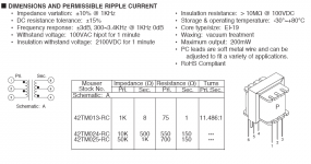
carpenter said:Here are the three inductors I ordered today from Mouser (there's so many ways to play with these things):
I've played with the 42TM025 so far. It has 350 ohms resistance on each primary leg; it also has 4H on each leg!
I lost nearly two volts output--down to 6 volts out. It seems to perform well; the upper sibilance hasn't diminished. My ears, I know...😀
Sine wave appears normal at 1000hz. I'll get back with more info when collected.
BTW, these are tiny critters, less than 2.5 cm in all directions.
Attachments
What else do you have in mind ?carpenter said:...42TM025 so far....
You use this number in your DC calculationscarpenter said:... It has 350 ohms resistance on each primary leg...
Just what is the voltage at the drain? It went up???carpenter said:I lost nearly two volts output--down to 6 volts out...
The spec says 300-3.4kHz? this could be a problem???carpenter said:...Sine wave appears normal at 1000hz...
😀 😀 😀
flg said:
The spec says 300-3.4kHz? this could be a problem???
😀 😀 😀
nope - if you use it as a choke
Zen Mod said:
nope - if you use it as a choke
That's what I was hoping, and it sure seems as if you're correct. The combo has a remarkable sound--especially when you figure the choke only cost 2 bucks! Good grief, I can only imagine how it would sound with audio quality chokes.
I'm going to wind a pair...someday.😀
flg said:
What else do you have in mind ?
You use this number in your DC calculations
Just what is the voltage at the drain? It went up???
The spec says 300-3.4kHz? this could be a problem???
😀 😀 😀
I have 5 other combinations using the three transformers I listed.😉
How would I use the choke resistance in my DC calcs? I just assumed that what is--IS.
The drain voltage was 7.8 volts, it's down to 6+ volts. Still sounds great, but without the monster Plitron in the background. Now the Plitron can resume its duties of supporting the foundation in the SW wing of my house!😀 😉 😀
Specs only apply to transformer application, not choke.
This is really a bunch of fun.
Now, the next project will include cascoding the whole kit-n-kaboodle to run more voltage on the upper rail--then it goes to a pair of F4s per side in balanced mode.
And one of these days, I'm going to build Choky's pumpkin...for sure!🙂
Now, the next project will include cascoding the whole kit-n-kaboodle to run more voltage on the upper rail
When you do this, consider trying two variations: one with a CCS feeding the differential pair, the other variant a resistor feeding the differential pair.
I found I liked the resistor better, but in hindsight, I am not sure if I changed the rail voltages from 40 to 60 when I made that change......
JJ
jupiterjune said:
When you do this, consider trying two variations: one with a CCS feeding the differential pair, the other variant a resistor feeding the differential pair.
I found I liked the resistor better, but in hindsight, I am not sure if I changed the rail voltages from 40 to 60 when I made that change......
JJ
Was your CCS on the upper or lower rail? I'm currently using a CCS on the lower rail.
carpenter said:
I'm going to wind a pair...someday.😀
A highly recommended adventure into the world of very high fidelity 😀
If you shop the intelligent way, you can make a kick butt solution for like 200 usd for a hefty pair, including all the right chemistry and so forth.
Magura 🙂
Magura said:
A highly recommended adventure into the world of very high fidelity 😀
If you shop the intelligent way, you can make a kick butt solution for like 200 usd for a hefty pair, including all the right chemistry and so forth.
Magura 🙂
Hi Magura,
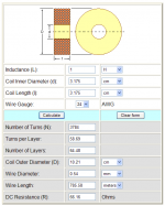
I was thinking of using 26 gauge wire (pretty small). I could wind a 1H air-core choke that has around 125 ohms resistance. What do you think?
carpenter said:
Hi Magura,
I was thinking of using 26 gauge wire (pretty small). I could wind a 1H air-core choke that has around 125 ohms resistance. What do you think?
I'm thinking that you have not calculated how much induction is needed to reach 20Hz 😀
Magura 🙂
Magura said:
I'm thinking that you have not calculated how much induction is needed to reach 20Hz 😀
Magura 🙂

Magura said:
I'm thinking that you have not calculated how much induction is needed to reach 20Hz 😀
Magura 🙂
Zen Mod said:
OK, smarty pants, which one of you scholars wants to go first? I haven't a clue how induction at 20k hz is calculated.
Edit: Nelson mentions using a 1H coil of wire, so I thought this might be a good place to start.
I've noticed that 125mH works and that 4H works. Which is best? I don't know.......
carpenter said:
OK, smarty pants, which one of you scholars wants to go first? I haven't a clue how induction at 20k hz is calculated.
Edit: Nelson mentions using a 1H coil of wire, so I thought this might be a good place to start.
I've noticed that 125mH works and that 4H works. Which is best? I don't know.......
www.vt52.com
lookie for xls files ......... theyre maybe zipped
Zen Mod said:
Thanks for the tip; I've downloaded and explored. Is Rp the equivalent of Drain resistance. If so, would this be the choke resistance in my application?
carpenter said:
OK, smarty pants, which one of you scholars wants to go first? I haven't a clue how induction at 20k hz is calculated.
Edit: Nelson mentions using a 1H coil of wire, so I thought this might be a good place to start.
I've noticed that 125mH works and that 4H works. Which is best? I don't know.......
I havn't always been smarter than you
http://www.diyaudio.com/forums/showthread.php?postid=306538#post306538
Magura 😀
Magura-
Of course, you know the correct answer was 6 ohms?
Woodie-
The CCS is on the lower rail feeding the sources of the input fets. I have never tried using a CCS as a load. Or an inductor, for that matter -- but I hope to try the 'choke loaded' version soon.
Neat thread!
JJ
Of course, you know the correct answer was 6 ohms?
Woodie-
The CCS is on the lower rail feeding the sources of the input fets. I have never tried using a CCS as a load. Or an inductor, for that matter -- but I hope to try the 'choke loaded' version soon.
Neat thread!
JJ
- Home
- Amplifiers
- Pass Labs
- JfetBOZ mods