The 2Sk30 may work in this application. How well/badly it might work I can't say, as I have no access to models for the part and no great incentive to try, as I have none myself. All I can say is that if one is sufficiently motivated, they can match up a set and post results here. Actual component values will depend on the IDSS ranking of the parts in question. Keep in mind that I looked at loaded SRPP results for parts like the J110 and 2SK170, and in this particular application, the PN4393 was far better in simulation than either of the others. I think that this SRPP application is best suited for parts with low to medium transconductance.
I don't understand the resistance to using the PN4393, as they are still readily available from catalog distributors at a relative pittance, meaning one doesn't have to spend a huge amount of money to gather a sufficiently large population of devices to make near-exact matching possible. The family specs (grab an old Siliconix JFET catalog for that data) for the device indicate that reasonably low noise is inherent in the device construction. I certainly haven't had any problem with the MM cartridges for which this preamp was designed. If you want to putter around and use another device, do so and let the rest of us know how it works. The circuit is simple enough to throw together on a piece of perf board.
I haven't done a whole lot of work on this project lately, as I have many other fish to fry. Some day, I'll get back to it. I won't post a parts list, as I build with what I have available to me from surplus sources or other scrounging. You're on your own there... This is DIY Audio, after all.
I asked about 2SK30 because 2SK30 is available here.
I am interested in your Post #56 where you mentioned about SRPP redesign and the simulation results.
But only input stage is shown there. Could you show whole circuit including output circuit?
I am interested in your Post #56 where you mentioned about SRPP redesign and the simulation results.
But only input stage is shown there. Could you show whole circuit including output circuit?
From what I can tell from the Toshiba spec sheet, the 2SK30 is similar in many characteristics to the 2N5457-5460, especially in terms of gain and IDSS range. The breakdown rating of 50V makes it a much more easily used part than the 2N5457 series. The lower gain makes it more suitable for the second type of SRPP circuit shown farther back in this thread, with a more modest capacitively coupled fixed load and a follower. Depending on what IDSS ranking you have, I would start with trying to closely match parts for VGS at a drain current of 2-3 mA. This will still yield a circuit with respectable distortion performance. The 2SK30 could also be used in the follower needed with that particular SRPP circuit, again with drain current of 2-3 mA. Use a capacitively coupled load of ~ 27k for the SRPP stages
One more thing regarding the 2SK30 - the useful device ranks would be the Y (1.2-3 mA IDSS) and G (2.6-6.5 mA IDSS).

Hi, nice mod. I think he uses J113 cascoded in his OBH-8SE? Do you have any idea of the en with BF244A and the Rs value you use? Also, why you have chosen an SRPP output too, over his constant current sourced emitter follower? The 15K across output is to ensure some ideal load for that SRPP? Any particular reason you have broken the passive network he used to employ as a whole in the first stage into two places? Most importantly, did you build and test it? Any measurements for noise floor, THD, etc.?
Hello Salas!
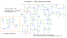
1) Alex Nikitin wrote, that applied BF244A, BF245A, J113 ect.
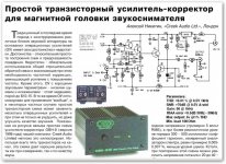
Typeselection of transistor : J-FET must have U(gs) min. - 0,5V (falling on Rs) and I(d)=1-4mA in an operating point!
I think, capable of working in this chart 2N3819, 2N4220, 2N5248, 2N5458, MPF102...
A simulator it confirms.
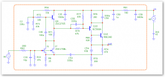
2) the Second cascade has a structure of SRPP, because this circuit technology provides good linearness and as a result are small distortions without a general feed-back.
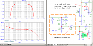
3) Loading of 15к is used for the test of chart (most not advantageous mode), real loading: 22-47к (entrance resistance)
4) On a chart 2 varians of correction are indicated 75ms, what from them to use - depends on inductance of MM of cartridge and Your taste.
This RIAA preamp - a simulation only, I did not build him.
Noise of cascade will depend on noise of J-FET and value R(s).
Best regards,
Alex.
1) Alex Nikitin wrote, that applied BF244A, BF245A, J113 ect.
Typeselection of transistor : J-FET must have U(gs) min. - 0,5V (falling on Rs) and I(d)=1-4mA in an operating point!
I think, capable of working in this chart 2N3819, 2N4220, 2N5248, 2N5458, MPF102...
A simulator it confirms.
2) the Second cascade has a structure of SRPP, because this circuit technology provides good linearness and as a result are small distortions without a general feed-back.
3) Loading of 15к is used for the test of chart (most not advantageous mode), real loading: 22-47к (entrance resistance)
4) On a chart 2 varians of correction are indicated 75ms, what from them to use - depends on inductance of MM of cartridge and Your taste.
This RIAA preamp - a simulation only, I did not build him.
Noise of cascade will depend on noise of J-FET and value R(s).
Best regards,
Alex.
Thanks for the reply. Is there any link for the original Radio Hobby article published in Kiev? Is Alex Nikitin Ukranian or Russian by the way?
P.S. I measured a BF245A for on resistance and its about 300 Ohm for 2-2.5mA IDSS. That and your source resistor gives me an estimation for about 5.4nVrtHz input noise equivalent. That is without R16 that will take it to 8 nVrtHz! I would lower the gate stopper or discard it if it does not oscillate in practice. I would not push it for MC in other words with such en, although it can give gain if you want. Would do better with higher impedance MM carts as for noise. 1K and over source resistance carts.
P.S. I measured a BF245A for on resistance and its about 300 Ohm for 2-2.5mA IDSS. That and your source resistor gives me an estimation for about 5.4nVrtHz input noise equivalent. That is without R16 that will take it to 8 nVrtHz! I would lower the gate stopper or discard it if it does not oscillate in practice. I would not push it for MC in other words with such en, although it can give gain if you want. Would do better with higher impedance MM carts as for noise. 1K and over source resistance carts.
Hello Salas!
Alex Nikitin is russian.
On this board his name is x-pro
Here his themes.
"Creek Audio Ltd.",
February 1999, London (Google translate RU/EN)
This theme, must be very interesting for you.
Non-feedback parametric linearisation in FETs
Best regards,
Alex.
Alex Nikitin is russian.
On this board his name is x-pro
Here his themes.
"Creek Audio Ltd.",
February 1999, London (Google translate RU/EN)
This theme, must be very interesting for you.
Non-feedback parametric linearisation in FETs
Best regards,
Alex.
Attachments
Last edited by a moderator:
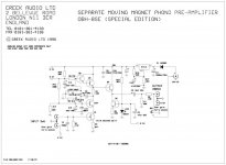
Thanx Alex, I was aware of his OBH style CCTs even presented as Cambridge plug in phono for A3i he did for them. I am also aware of is JLH inspired phase splitter and TTL Mosfet same sex output stages. He has presented also here in old threads. I was more interested if you got a copy or url of the phono article he presented in ''Radio Hobby'' magazine, I believe a Ukranian publication.
Hello Salas,
''Radio Hobby'' is this printed edition.
Official links are only on self edition, but not on a publication
... but, Salas - link.
N3 1999 , page 48
Radiohobby Forum
Best regards,
Alex.
''Radio Hobby'' is this printed edition.
Official links are only on self edition, but not on a publication
... but, Salas - link.
N3 1999 , page 48
Radiohobby Forum
Best regards,
Alex.
Nice. Thanks. I can read the forum somehow with the auto translation.
P.S. I found thread ''vinyl-corrector'' way cool term to call a phono stage.
P.S. I found thread ''vinyl-corrector'' way cool term to call a phono stage.
Hello friends!
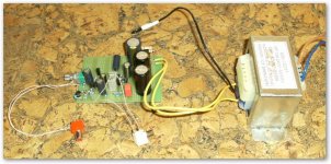
I tried to do a new first cascade.
In a chart applied a feed-back, excuse..
I can not estimate noise, construction "on wires", it is a model.
Results measuring very near to MicroCap.
Look, what I have in the end :
I tried to do a new first cascade.
In a chart applied a feed-back, excuse..
I can not estimate noise, construction "on wires", it is a model.
Results measuring very near to MicroCap.
Look, what I have in the end :
Attachments

What does this have to do with a JFET SRPP circuit? If you wish for people to discuss your design, start your own thread.
On topic - coming up soon is the next revision of this (SRPP) concept using PN4393 for first stage and (perhaps) 2SK30 for second stage, with PN4393 buffers all around. Those of you who are still whinging about PN4393 (readily available from Mouser & Digikey at ~30 cents apiece for the quantities needed to get the really matched pairs for this project) might want to look at the 2SK117. I just picked up 200 pieces of both the SK30 and the SK117 on Ebay from a Hong Kong seller. Time and usage (and some testing) will tell whether these are the real deal or relabeled junk.
At any rate, I just finished the layout, and schematic will follow when when I work out precisely what I want to do with the values in the second stage. The first stage using SRPP PN4393 and source follower yields vanishingly small distortion (simulated) for low level inputs (check back earlier in this thread for the basic simulation in PSpice). The gain is higher than I like to see for the first stage,(around 70X, if I remember correctly), so the gain on the second stage will need to be pared down accordingly. One way to do this is to use a lower gain fet in the second stage. I'll use my "2SK30s" for that purpose, but simulate with something like the 2N5459, which has similar characteristics (I also have the model). The PN4303 is also similar, and these are still available in Fairchild flavor from Mouser. Anyway, schematic will follow when I get things worked out to my satisfaction.
This is not a project for the kitbuilders, but the circuit has rewards for those with persistence who are not afraid of building their own breadboards and matching their own fets.
Last edited:
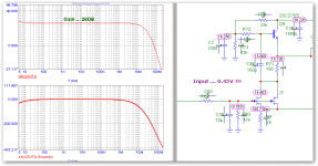
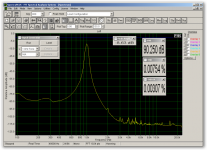
This is the piece I needed to finish the next revision of the SRPP RIAA amp. The simulation uses PN4303, as that's the model I have. 2SK30 could probably be subbed. This stage gives me a gain of ~20, which will match ok with the first stage, which will use a PN4393, one of my favorite workhorse fets, no matter how much everybody else whinges about it.
Anyway, attached is a simulation of a loaded SRPP stage using the PN4303. As you can see, high level distortion simulation is ok, and may respond to further tweaking. Things to tweak - quiescent current in the SRpp stage, and the capacitively coupled load at its output. This circuit might also work using 2N5459 in the SRPP input stage. Keep in mind, however, that the 2N5459 has a breakdown voltage of only 25V, so the supply voltage would have to be lowered to use it, sacrificing some dynamic range.
Anyway, attached is a simulation of a loaded SRPP stage using the PN4303. As you can see, high level distortion simulation is ok, and may respond to further tweaking. Things to tweak - quiescent current in the SRpp stage, and the capacitively coupled load at its output. This circuit might also work using 2N5459 in the SRPP input stage. Keep in mind, however, that the 2N5459 has a breakdown voltage of only 25V, so the supply voltage would have to be lowered to use it, sacrificing some dynamic range.
Attachments
Last edited:
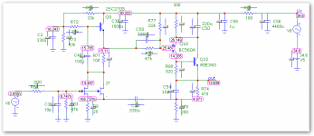
Some more messing around in PSpice using the 2N5459 model yielded better results. I think I will try populating this stage by selecting from the Ebay 2SK30A units I have on hand, whose characteristics are similar. The first stage will still be built using all selected PN4393.
Attachments
Last edited:
The 5459 is a handy Fet, I use it in cascodes and current sources. Its noise can be 3-5 times more than the K117 you ordered though. BF245B is half noisy than 5459. K117 has best gm/pF in the Toshiba line and its low in noise closer to the K170.
The 2SK117 and 2N5459 aren't really close in characteristics. The 2SK30A is a better match for the 2N5459, and more useful with its 50V VD rating, vs. only 25V for the 2N5459. The 2SK117 is a better match for the PN4393. I'm not sure whether the 2SK30A and 2SK117 I purchased are genuine, but I will cautiously try them out. I still favor the PN4393 as I have a bunch, and I know they're genuine. The new board is about 2/3 stuffed. I'll continue matching fets after Thanksgiving dinner tomorrow. I don't have any BF euro-fets at present.
- Home
- Source & Line
- Analogue Source
- JFET SRPP RIAA Preamp