wrenchone
I can see you know a lot, and do extensively testings and simulations on RIAA amps. I will wade trough some of your posts and learn some more, thanks for sharing. 🙂
This is all interresting but i have to wait with experiments because of all other projects going on.
This forum is addictive ... big time
I just got my new JFET SRPP module fitted into my test preamp, and I'm impressed, even using my 5th best amp and 5th best speakers. I'll need to build new speakers just to test its capabilities.
Good to know. What are the main characteristics that grabbed your attention? Some picture will be nice too.
Pictures not available, as the amp is under wraps now. The test preamp enclosure it's a part of is nothing special, being a standard-issue utility box with a few wires and connectors hanging off of it. When I get something that really satisfies me, then it's time for a nice case. I'll leave more detailed descriptions of the sound until I get a chance to audition at BA with some better components in the reproduction chain.
I wish you good auditioning and lots of hobby fun at the BA. I did not mean a picture of a nicely looking finished machine, just your work in progress.🙂
Ok, great. After BA you will have a richer experience of its characteristics. Its a very original circuit and components (FET) choice.
Ok, great. After BA you will have a richer experience of its characteristics. Its a very original circuit and components (FET) choice.
I'm still very pleased with the present incarnation of the JFET SRPP preamp, though the overall gain is a little on the high side compared to my other input sources. I trhink it's working synergistically with my latest power amp, a singled-ended amp employing screen driven 6CD6GA sweep tubes. This power amp is documented in the tubes section of this forum. Try searching using the terms "6CD6GA enhanced triode". The sound is very open and lifelike, and imaging is good. I'll have to improve my speakers to fully take the measure of the amp/preamp combination. Unfortunately, I was not able to audition the preamp at this year's Burning Amp, though I was able to try out a couple of tube power amps with various speakers.
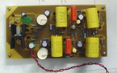
Sice the preamp I'm currently using is hack job cobbled from a previous project, I decided to construct a cleaner version powered using an on-board fast shunt regulator. Schematic will follow when I get it documented, but attached is a picture of the new board.
Sice the preamp I'm currently using is hack job cobbled from a previous project, I decided to construct a cleaner version powered using an on-board fast shunt regulator. Schematic will follow when I get it documented, but attached is a picture of the new board.
Attachments
Attached is the schematic for the current version of the JFET SRPP. FETs for the SRPP cells require precise matching, which means you need to buy a fairly big pile of FETs. The good news is that the FETs usable in this circuit are cheap. A sorting jig using a current sink and a pair of 9V batteries is useful in the sorting process. You'll need a 2mA current sink and a 10 ma current sink, the 2 ma sink for selecting the SRPP FETs, and the 10 ma sink for selecting fets for the followers. The meter you use for sorting should be capable of resolving 0.01V.
The quickest way of going about things is to sit down with the FETs and a sheet of paper, and start sifting devices by Vgs at 2ma drain current. Write the Vgs on the paper, and set the FET down by the number. As you characterize FETs, you'll notice little groupings begin to emerge. I based the circuit shown on four pairs of FETs that tested out at 1.02V Vgs at 2 ma drain current. Either 499 ohms or 511 ohms would be suitable as values for the source resistors to set drain current at ~2 ma for 1.02V Vgs - I happened to have a bunch of 499 ohm resistors handy. The other FET pairs in the circuit are set in a similar fashion.
For the single FETs used as current sources in the power supply, it is acceptable to check Vgs at the required drain current and use an appropriate resistor value depending on Vgs, as no matching is necessary.
Attachments
Excellent engineering. Congratulations. I see that you kept on evolving your shunt reg. What is its final performance for ripple rejection and broadband noise? Any measurements or simulation indications? Can you describe its functioning? We are on the look for a good supply on my Simplistic NJFET RIAA thread, and we would appreciate any input and experience.
I haven't done any noise or rejection measurements on the regulator so far - it was designed for speed and low impedance. I showed some sims in a thread called "Regulator for RIAA preamp and line amp".
Thank you. I do believe that those two parameters are the priority too. At least for not extreme gain RIAA. I will look in to your thread.
Given that the regulator has high bandwidth, and the diff pair are 2SJ74s (very quiet), the overall noise level will be dictated by the reference. The LEDs are pretty quiet, but maybe a packaged reference can be found that whould be quieter. If it doesn't fatally compromise the stability, a lead network across the top half of the voltage divider network would also help.
I thought I should addthat given the high impedance of the FET differential stage, the opportunity exists for adding some RC filtering between the reference and the FET gate without unduly compromising things.
With your RIAA gain, I doubt that you need even better noise performance. On the other hand using the RC is classic there, I don't think it may hurt anything. You would be very unlucky to get any odd side effect.
Pop goes the weasel... This is the thread that wouldn't die.
This afternoon, I was searching around the Web for other mentions of SRPP JFET preamps, and stumbled across a PDF of the Elektor article on their JFET SRPP preamp. It turns out that they used high gain FETs and tamed the resulting gain with a capacitively coupled resistive load. (Sound familiar?). The passive RIAA equalization is developed across this load resistor. Armed with this information, I did some simulations on an SRPP gain cell using my trusty old friend the PN4393, still readily available from Mouser and Allied Electronics in several flavors.
After some fiddling about, the results were shockingly good. Attached is a schematic and Fourier plot to illustrate. I wouldn't expect to get anything quite as good as the posted results in real life, but anywhere in the vicinity is mighty fine territory to be in....
Surprisingly, results using the J110 and 2SK170 weren't anywhere near as nice (not by a factor of ten), though some more fiddling might improve them some. These are very good numbers to get from a 35 cent FET (and that's the price of the expensive brand). The load resistor shown gave me a gain of about 60X. The thing that got me to ultra-low distortion land was upping the quiescent current some. Again, the numbers I got are for indication purposes, since they come from a simulation and not a real-life measurement. Still, they are good enough to make me want to try an all-4393 preamp.
BTW - to answer various queries in advance, I do not and will not have a board available for this circuit. I don't have the time or inclination to deal with it - I barely have enough time for my own endeavors, with work, a volunteer DJ gig, and other circuit hacking. The thing is easy enough to put together using perf board.
Attachments
I took a closer look at the Elektor article, and came out with the following observations:
1) The designer used a source follower front end to drive the Miller capacitance of the SRPP input stage, which used a 2SK389 (rather significant gate and reverse transfer capacitance). Not a bad idea, but the input follower used a simple resistor to ground. If I chose this approach, I'd rather use active loading, even at the cost of a negative supply. The more jesuitical among us may argue that it doesn't make much difference either way, as the input signal swing is so small. Then again, the designer used a 2SK389 for the follower, which still has a lot of gate-to-source capacitance. The PN4393 has a lot lower gate and reverse capacitance than any of the other popular low noise fets. Another approach may be to cascode the bottom fet of the SRPP gain cell. I'll try that next week in simulation and see what happens.
2) The designer built the RIAA network around the SRPP load resistor. to do this, you need to know the SRPP output impedance, as it is a part of the network. The isolation capacitor for the load resistor was too small, and it shows up in the low frequency RIAA error. I plan to build up a gain cell and test the actual output impedance so that I can properly calculate the RIAA network values. The load coupling capacitor will also be much larger (~20 uF).
3) the designer used a funky feedback scheme around the output SRPP that loads the RIAA network (and it's global feedback...) I'll try just duplicating the input stage and adding a current source loaded source follower.
The result - an all PN4393 preamp (with maybe a PN4391 for a cascode). More later.
Hi,
Could you post the PCB diagrams and parts list too as it will be really helpful ?
Best regards,
Bins.
Could you post the PCB diagrams and parts list too as it will be really helpful ?
Best regards,
Bins.
How about to use 2SK30 instead of PN4393?
When can I see your final SRPP circuit? I'm now waiting for your result.
Rothko.
When can I see your final SRPP circuit? I'm now waiting for your result.
Rothko.
How about to use 2SK30 instead of PN4393?
Nice part - thanks for the hint! From what I see a nice replacement; for what it's worth, even the 2SK246 can be used. But unfortunately its noise is not spec'd.
Have fun, Hannes
- Home
- Source & Line
- Analogue Source
- JFET SRPP RIAA Preamp