Andrew,
Great that the offset drift is gone...guess the source resistors are mandatory.
I would be sure to try it with and without the rail filter between the vas and output. So far Mike likes it with and I like it without...
Great that the offset drift is gone...guess the source resistors are mandatory.
I would be sure to try it with and without the rail filter between the vas and output. So far Mike likes it with and I like it without...
offset drift is still there.Great that the offset drift is gone...guess the source resistors are mandatory.
It's the offset runaway at start up that appears to have gone.
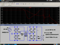
As I reduce the supply voltage from +-31Vdc to +-24Vdc the near zero offset increases to >+100mVdc offset.
Variable mains voltage will vary the output offset.
This amp needs better control of offset.
I shall repeat that Vdc vs offset experiment with the first build to see if it was similar.
I am going to squeeze in 0r1 to that first build to see what difference that makes.
If that improves the runaway then I will alter this second build.
Last edited:
which one, or both?I would be sure to try it with and without the rail filter between the vas and output. So far Mike likes it with and I like it without...
World Audio Design (WAD) did a tube amp with toroids for both the mains and the output transformers.I never ever experienced a shootout where toroid's won a listening test against conventional transf. or Lundahl. Even Plitron's do sound dark, foggy, slow & muddy as if someone killed the transients. I shudder even in remembering the sound of toroid's in tube amps.
It was offered as a kit by HiFi World. Quite a few were sold.
A couple of months down the line, WAD offered a redesigned kit with the output transformer replaced by an EI. The toroid did not have sufficient inductance.
The toroid mains transformer was retained.
I bought the new EI/toroid version of the KEL80.
which one, or both?
I use both legs & both positions
20R + 470u, pos & neg rails, between o/p & VAS
0.1R, pos & neg, between PSU smoothing caps. ( 4 x 0.1R in total per channel ) as per Hugh's PCB
Mikel, you should try using a common-mode choke in your power supply. These can be gotten easily out of switching supplies and old CRT devices, especially projector televisions. Hmm, I have some of those too, I may try wiring them up.
- keantoken
- keantoken
I think my stuff will arrive tomorrow. Then I will ensue with a dangerous hurricane of all the things I've thought of since my iron tip burnt away, reined in only by my apathy, laziness and need to sleep. I will have a nice stock of BC550C/560C and 2N5551Y/5401Y, two very good pairs I think. And now that I have these, I will be wishing I also had something else, and so on...
- keantoken
- keantoken
Keantoken,
My system is headed towards being double insulated rather than earthed.
At present my system is only earthed via the MDF touching the heat sinks and the mdf touching my wooden floor - in other words only a very high impedance earthing.
In these circumstances I think common mode noise will be invisible to my amps as there is no solid reference for it to interact with.
Do you agree ?
It is not for common-mode noise. It reduces noise from the mains and filters out diode glitches. See attached.
- keantoken
- keantoken
Attachments
Last edited:
choke regulation
keantoken,
Oh yes, that's similar to how i've done my choke regulation - that I just finished - only I did it like Hugh did the CRC in his cct just replacing the resistors for with inductors ( I used four 12V + 12V 200VA transformers ) and 32,000uF after them.
. . . and in case you are wondering the sound is pretty amazing.
Now I feel I have a power supply that I can just forget about and that enables me to get on with optimising the amp design on a very solid & silent basis.
oh and by the way, I tried listening to my speakers just now with the amps on but nothing connected there is no perceptable noise of any kind from the speakers, neither hiss or hum - but my gain is set to x 11 so perhaps this will be helping a bit with these very nice low noise levels.
mike
Last edited:
Mike,
There is a way you can use a common mode choke - which can be viewed as a 1:1 transformer in fact - on the supply rails between the filter caps.
This component creates a mutually coupling magnetic circuit which nulls noise appearing on both rails, just as KT has drawn it. So, a current pulse on one winding, say serving the positive rail but also appearing on the negative rail, will be transformed into a magnetic pulse which depresses the current pulse on the other rail, and vice versa. These are very effective, and I use them on one of my commercial amps. Coilcraft make these small chokes - strongly recommended.
Are you using about 5mH?
Hugh
Hi Hugh,
My chokes are just like in KT's diagram only I use them in the earth legs also just like your CRC arrangenment published earlier in this thread.
I would be interested in small because although my supply is now very good indeed it certainly isn't either small or light or cheap. Thanks for that I will check their site.
I am using 12V + 12V as 1:1 transformer type mode as you describe the inductance is 3mH per winding which adds up to 12mH when they are operating in series.
I imagine that 15V + 15V would give about 5mH
cheers
mike
Correction:
My chokes are not in common mode - I may be a bit thick but for my purposes I don't see much point in common mode chokes as I explained earlier. KT said they don't act against common mode noise but it seems to me that is precisely what they do do and common mode noise is not as issue for me at present . . . . but perhaps I need a lesson in chokes coz I have heard people talking about common mode chokes for ages now and I never did really see what they are for unless on is trying to prevent noise with reference to an earth and my at present my entire system is pretty much floating with respect to earth.
My chokes are not in common mode - I may be a bit thick but for my purposes I don't see much point in common mode chokes as I explained earlier. KT said they don't act against common mode noise but it seems to me that is precisely what they do do and common mode noise is not as issue for me at present . . . . but perhaps I need a lesson in chokes coz I have heard people talking about common mode chokes for ages now and I never did really see what they are for unless on is trying to prevent noise with reference to an earth and my at present my entire system is pretty much floating with respect to earth.
Mikelm,
Since you are experimenting with inductors I thought I would let you in on a little idea of mine. Years ago when I was fiddling with Tesla coils I had to make some RF chokes. I found a very simple and effective way to do this was to wrap a few tens of turns around the large round ferrite from the back of a CRT TV or computer monitor.
It's quite amazing how much inductance you get per turn from that particular ferrite, and the material is well suited to filtering out noise.
Might be something to try if you're bored and want to go hardcore DIY!
Thx Greg, that's the kind of tip I'm happy to know about.
I always thought that a ferrous metal was one that contained iron.
So I thought ferrous was reasonably synonymous with iron.
So I wonder what is the difference between iron power & a ferrite.
cheers
mike
I always thought that a ferrous metal was one that contained iron.
So I thought ferrous was reasonably synonymous with iron.
So I wonder what is the difference between iron power & a ferrite.
cheers
mike
I guess you mean iron powder, Mikelm. They are similar in their preparation, by tabletting iron powder in a press and then sintering (fusing). it in a furnace.
Ferrites are a mix of other metal compounds with the iron to form new compounds with different magnetic properties such as might be more suitable for use at higher frequencies, or better linearity in filter applications. The ferrites used as magnets in loudspeakers and those used in VHF coils will be quite different formulations but still with the same type of process. Google Fair-Rite for data on the specifics.
Ferrites are a mix of other metal compounds with the iron to form new compounds with different magnetic properties such as might be more suitable for use at higher frequencies, or better linearity in filter applications. The ferrites used as magnets in loudspeakers and those used in VHF coils will be quite different formulations but still with the same type of process. Google Fair-Rite for data on the specifics.
I discovered those flyback cores were quite useful for sharpening knives to a polished edge... These cores must be useful, since often there are two almost identical halves and a metal clip which holds them together.
- keantoken
- keantoken
Ferrites are a mix of other metal compounds with the iron to form new compounds with different magnetic properties such as might be more suitable for use at higher frequencies
thx
- Status
- Not open for further replies.
- Home
- Amplifiers
- Solid State
- JFET input, MOSFET VAS, LATERAL output = Perfect!!