Another precious gift to DIY community
Hi Lineup, Swordfishy, Hugh, Mikelm and MiiB,
Many thanks to you all for this precious gift. This thread is a nice read for all the amateurs because of the simplicity of the circuit and many contributions about stability, distortion and square wave response from all the great minds. This is so simple even we can build it on a perf board.
Another version using IRFP240/9240 is very useful to builders to experiment with these relatively cheap MOSFETs. To use IRFP240 and IRFP9240 in the output, is that ok to replace this output stage with the one mentioned in post #29 including Vbe multiplier?
Thanks,
Rao
Yes it can be used with IRFP240/9240.Hi Lineup, Swordfishy, Hugh, Mikelm and MiiB,
Another version using IRFP240/9240 is very useful to builders to experiment with these relatively cheap MOSFETs. To use IRFP240 and IRFP9240 in the output, is that ok to replace this output stage with the one mentioned in post #29 including Vbe multiplier?
Thanks,
Rao
In fact some month ago I did such a schematic of this amplifier.
One thing though.
VAS stage for IRFP240 should have at least 10 mA that runs through the VBE-multiplier.
It is good if it is 10, 15 or 20 mA.
THe other outputs ECX Exicon and 2SK1058 can have a VAS
with only 5 mA (or more)
My last schematic uses 10 mA for VAS stage.
It should be okay for IRFP240/9240.
Just add one IRF610 for VBE multiplier and replace the output devices.
I will post one such circuit.
Thanks
Fetzilla with IRFP240/9240 version
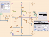
Here you are.
One think you notice, I use blue for adjustable components.
What you need to adjust for zero output and idle bias in output.
For example I have adjusted R3 for idle bias 200mA through IRFP240/9240.
Actually IRFP240 simulates a little lower THD (0.007%) than 2SK1058.
But difference is very small.
Attachments
Hi Lineup,
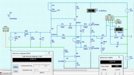
I notice on this one compared with the earlier one you have less distortion @ 0.007%
But on my cct I get less than 1/2 this at 0.003%
I wonder why this is. I set my o/p to 200mA VAS to 14mA and I/P to 4.5mA
here it is . . .
With 1 amp in o/p stage it drops to 0.001% @ 1 watt
I notice on this one compared with the earlier one you have less distortion @ 0.007%
But on my cct I get less than 1/2 this at 0.003%
I wonder why this is. I set my o/p to 200mA VAS to 14mA and I/P to 4.5mA
here it is . . .
With 1 amp in o/p stage it drops to 0.001% @ 1 watt
Attachments
Last edited:
I set often 100mA for 2SK1058. 200mA for IRFP240
And there are small differences in circuit.
I use 100 Ohm for IRF9610 emitter. You 47 Ohm.
ECX10N20 may have lower THD than 2SK1058.
you have 750/47 feedback
I have 3300/220 feedback
THe lower values in feedback, the lower THD.
We might have two different models for 2SK170BL
All these small differences can make the difference from 0.003% to 0.010%
I can get 0.002% if I want from this topology.
But then I have to add capacitance (220pF) to get it stable.
The official version need no compensation cap,
and have a little more THD because of this.
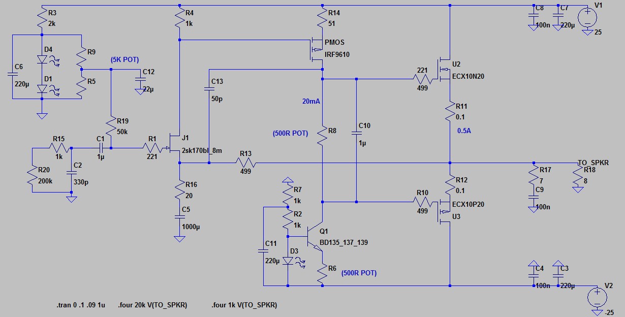
AC Analysis to make stability via compensation cap.
Look at the red curve.
It is without compensation cap.
Amplifier probably will oscillate.
Add the 220pF cap to IRF9610.
Result now is the green curve.
It is straight until a smooth slope.
Amplifier is stable. Compensation is done correctly.
Not too much capacitance.
Just enough to get a nice curve.
Look at the red curve.
It is without compensation cap.
Amplifier probably will oscillate.
Add the 220pF cap to IRF9610.
Result now is the green curve.
It is straight until a smooth slope.
Amplifier is stable. Compensation is done correctly.
Not too much capacitance.
Just enough to get a nice curve.
Attachments

I just noticed that as o/p stage current increases HD drops up till 292mA giving -98dB
After that HD gets steadily worse as current rises to 1A giving -96.6dB
Hardly any difference I know but interesting to find that sweet spot
Swordfishy - how high did you take the current when you said the sound got sweeter with more current ?
After that HD gets steadily worse as current rises to 1A giving -96.6dB
Hardly any difference I know but interesting to find that sweet spot
Swordfishy - how high did you take the current when you said the sound got sweeter with more current ?
Maybe ideal current for ECX10N20 is like 250mA.
Usual idle current for MOSFETs can probably be from 100 to 300mA
Also depends how hot we want the heatsink to be.
There is a limit for everything.
You should take measurements not only at 1kHz 1 Watt
The output level also will effect the result.
swordfishy runs 0.500A here:
Usual idle current for MOSFETs can probably be from 100 to 300mA
Also depends how hot we want the heatsink to be.
There is a limit for everything.
You should take measurements not only at 1kHz 1 Watt
The output level also will effect the result.
swordfishy runs 0.500A here:
Hi 🙂, what about using 2SJ79 or other lateral medium power MOSFET in place o IRF9610?
Should it increase linearity?
Should it increase linearity?
Hi Barmanekm,
The 2SJ79 has acceptable gate capacitance (around 120pF), a suitable power rating (up to 30W properly cooled) and voltage rating (200V) but its tranconductance is around 50mS at 20mA. This compares with the 170pF Ciss of the IRF9610, similar power and voltage ratings, but a transconductance of no less than 900mS, more than an order of magnitude higher. In fact, the IRF is a vertical mosfet, and the 2SJ a lateral mosfet. Incidentally, the Vgs of the 2SJ79 at 20mA is about 0.72 volts, a lot less than the IRF9610 which is just less than 4 volts. This affects the value of the gate/source resistor on the VAS, which in turn affects loop gain. For a smaller resistor, the loop gain would drop further again.
This would radically change the loop gain, down by around 25dB or more, and the amp would measure and sound different. Whether it would be an improvement sonically is the question; my thoughts are that it would sound tubey, not as crisp, and a bit warmer. You would have to decide personally if you preferred the view through sonic sunglasses....
Cheers,
Hugh
Last edited:
Lineup,
You are testing the miller cap concept, but have you tested the concept I posted in post 531 as suggested by Hugh? I think it is even better than a miller cap, and was far more effective for correcting overshoot than a 150pF miller cap.
You are testing the miller cap concept, but have you tested the concept I posted in post 531 as suggested by Hugh? I think it is even better than a miller cap, and was far more effective for correcting overshoot than a 150pF miller cap.
THat 50pF cap suggested by AKSA
was actually on my mind this morning.
I will do some SPICE with such cap from VAS to source of JFET.
Often such cap is attached with one resistor in series.
was actually on my mind this morning.
I will do some SPICE with such cap from VAS to source of JFET.
Often such cap is attached with one resistor in series.
I will try the 2SJ79 or some similar for VAS.Hi Barmanekm,
The 2SJ79 has acceptable gate capacitance (around 120pF), a suitable power rating (up to 30W properly cooled) and voltage rating (200V) but its tranconductance is around 50mS at 20mA.
-----
This would radically change the loop gain, down by around 25dB or more, and the amp would measure and sound different. Whether it would be an improvement sonically is the question; my thoughts are that it would sound tubey, not as crisp, and a bit warmer. You would have to decide personally if you preferred the view through sonic sunglasses....
Cheers,
Hugh
It all boils downto what SPICE Models I can get.
On the downside is the availability of 2SJ79. It cant be easy to find.
The amplifier should only have easy-to-get parts.
It looks like it's still in mass production from Renesas....But not sure about the validity of this page..??
Power MOSFETs for General Amplifier | Renesas Electronics
Power MOSFETs for General Amplifier | Renesas Electronics
I have been interested to hear from different people here that various measures either increase or decrease higher order HD so I decided to have a look at that in spice.
I am cautious to state these findings as definitive because I don't fully trust spice but as I stated earlier that HD seems to be lowest @ about 300mA bias I thought I should add this new, fuller perspective.
I tried different o/p devices.
I tried swapping i/p jfet load resistor for CCS thus adding about 6dB olg
I tried adding a Hawksford cascode with both resistor / CCS and pure Voltage to provide the voltage rise.
The o/p level was set 10V peak because for me this is a typical high level I would use.
In Fourier I analysed up to 20khz
I tried all of the above measures with different o/p bias currents and what I would say to summarise the findings was that the hawksford cascode & i/p stage CCS slightly changed the signature of the higher orders of HD but did not substantially reduce or increase it.
But . . . . what did have a huge impact on higher order HD was simply raising the o/p stage bias current.
I think that I have established that at low bias currents 3rd HD is higher than 2nd but I would love some real world confirmation.
Adding an i/p stage CCS consistantly helped to give more 2nd and less 3rd
But across the board the one measure that seems to "fix" all these issues is biasing into class A. 1 amp seems to be enough to get very a significant improvement.
I would be interested to hear from Swordfishy about how high he biased his amp when he was testing. I seem to remember he said it sounded sweeter with higher bias but I could not find that when I looked for it.
All this has persuaded me to build with a larger heat sink so I can run this at at least 1A.
mike 🙂
Last edited:
Thanks Mike,
Interesting finds.
If you bias to 1A, and maintain 25V rails, you dissipate a total of 100W of heat with two channels.
A 300mm long x 75mm tall heatsink, a Conrad (made locally in Oz), weighs 1.05Kg and does 0.37C/W at 80C. At 40C, a more reasonable temperature, the thermal rating is not as good, around 0.42C/W.
Thus, dissipating around 100W, we are looking at a 42C rise above ambient.
This is fine for a cool room at 15C, but at 30C, a common room temperature in a subtropical environment, we are looking at 72C, which is too hot, as the junction temperature would be at least 30C over this.
MTBF is halved for each 11C rise in temperature, a quirky corollary of the Arrhenius equation. So really, we would need TWO of these MF30-75 heatsinks, one for each channel.
That's getting large, not to mention the wasted electrical power.....
I wonder what the relative amplitudes of the H5, H7 and H9 harmonics really are, vis a vis a bias level of 150mA?
It's surprising it all makes such a difference!
Cheers,
Hugh
Last edited:
There is a difference between Miller Cap and VAS-Source compensation.Lineup,
You are testing the miller cap concept, but have you tested the concept I posted in post 531 as suggested by Hugh? I think it is even better than a miller cap, and was far more effective for correcting overshoot than a 150pF miller cap.
However at 1 kHz 1 Watt the difference is very small, in favour of VAS-Source.
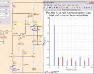
I setup a Fetzilla which need compensation.
180pF Miller was right.
820pF VAS-Source gave correct compensation.
Then I ran Fourier at them both and put at same graph.
VAS-Source gave THD 0.0024%
Miller gave THD 0.0028%
You can see the Fourier in my diagram below.
Conclusion.
The difference is there.
But is, at least at 1kHz-1Watt, so small it does not matter what we use.
If we have bigger value cap, we use 820p
Otherwise we use 180pF Miller normal.
Attachments
He used 0.5AI would be interested to hear from Swordfishy about how high he biased his amp when he was testing. I seem to remember he said it sounded sweeter with higher bias but I could not find that when I looked for it.
All this has persuaded me to build with a larger heat sink so I can run this at at least 1A.
mike 🙂
Which he also have put in his schematic I showed you on the last page.
He used 0.5A
Which he also have put in his schematic I showed you on the last page.
Yeah, but I thought he said he tried the bias at different levels
swordfishy - are you there ?
😉
p.s. Lineup: I see you also have H3 higher than H2
- Status
- Not open for further replies.
- Home
- Amplifiers
- Solid State
- JFET input, MOSFET VAS, LATERAL output = Perfect!!