That's getting large, not to mention the wasted electrical power.....
Here in UK where it gets quite cold we can heat our houses with our class A amps !
. . . and if our house is really well insulated this is the only heating we need !
p.s. Lineup: I see you also have H3 higher than H2
mikelm
That test was temporary Fetzilla with no emitter resistor for IRF9610
and the feedback divider was the lowest: 150/10 Ohm. (gain x15)
Such an amplifier has got high OLG, and so need compensation.
If you try the official Fetzilla with THD 0.010%
you will notice it has more H2 than H3.
HERE IS THE OFFICIAL FETZILLA
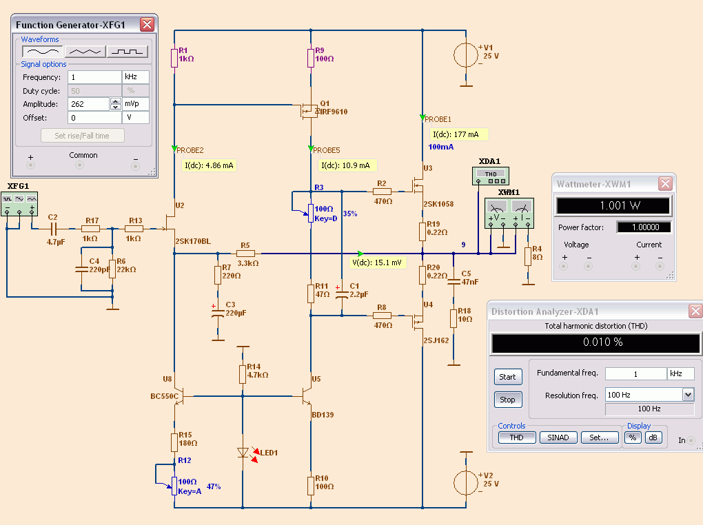
OFFICIAL FETZILLA
How do you determine which compensation is right...??
Can you do that in simulation.. Don't you need real circuits for that..??
Can you do that in simulation.. Don't you need real circuits for that..??
I did find that my simulations and swordfishy's tests for stability matched quite well.
Also I found in spice that for this cct a miller cap was not effective and swordfishy confirmed this.
So I think we can get a good idea from spice.
Also I found in spice that for this cct a miller cap was not effective and swordfishy confirmed this.
So I think we can get a good idea from spice.
As a general rule, you should gun for H2>H3>H4>H5 and so on, according to Jean Hiraga.
In my experience you can get a good idea from Spice IFF the models are good.
Stability analysis is possible with Spice also, if you use Middlebrook analysis. But again, you should test it with a Quad electrostatic, quite the biggest bitch of a load I know....
You should, however, always build and audition the amp with many ears, not just your own, and diverse musical selections as well.
Cheers,
Hugh
Mikelm,
Yes I have tried 1 amp and I prefer it there, but I was trying to find a compromise between livability, reliability and sound quality so I said to use 0.5A. You may recall that I was an advocate of a class a design from the very beginning! If I was in a cold country it would be my choice.
This is why I have stuck to 25v rails. I would rather have my dissipation consumed by extra current!
The same can be said for the vas. Sounds better at 25ma than it does at 10 in my opinion.
Last edited:
What ever happened to danspy? I want to know what other people think - I'm scared my ears aren't golden enough to be an authority on how this amp sounds.
I do AC analysis.How do you determine which compensation is right...??
Can you do that in simulation.. Don't you need real circuits for that..??
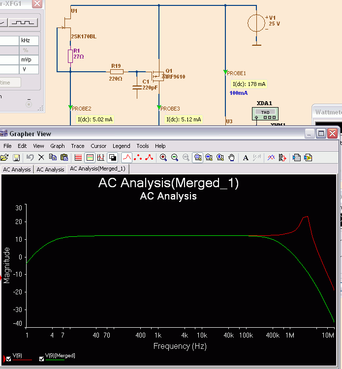
If there is an overshoot in AC curve, we can guess circuit is not stable.
On previous page I show how to use AC analysis.
True is that a real circuit seldom match the compensation done in SPICE.
But to compare 2 things is possible in SPICE. The relative value.
For example I had posted a circuit with 22pF
Danspy got oscillations until he useed 100pF.
So, compensation in SPICE has got a value on its own.
But should not be confused with a real circuit. At least when it comes to compensation.
What, swordfishy?????What ever happened to danspy? I want to know what other people think - I'm scared my ears aren't golden enough to be an authority on how this amp sounds.
You have not Golden Ears ... and you admit it!!!
I miss Danspy, too.
He built the first Fetzilla. I think he has built a stereo. He took pictures of it.
Hope he comes back.
The gilt on my ears wore off long ago, a relic of ageing, I believe.
However, I have many younger friends, who are entertained by fruit bats as they forage invisibly in the night.
I ask these guys, but they are a moving target, as their ears age too.
However, with my old, old ears I can still recognise a good system from 50 metres in seconds. If I can't hear it properly, I simply turn it up a few db. It's the processor, not the ears, I find.
Danspy, you must return. We need you.....
Hugh
As a general rule, you should gun for H2>H3>H4>H5 and so on, according to Jean Hiraga.
In my experience you can get a good idea from Spice IFF the models are good.
Stability analysis is possible with Spice also, if you use Middlebrook analysis. But again, you should test it with a Quad electrostatic, quite the biggest bitch of a load I know....
You should, however, always build and audition the amp with many ears, not just your own, and diverse musical selections as well.
Cheers,
Hugh
H2>H3>H4....
.
Regarding stability and compensation.
We have noticed that amplifiers of Hiraga, JLHood, Nelson Pass
not often has got compensation capacitors.
When you build you need not much worry about stability.
Classical Amplifiers of these gentlemen are most often without comp caps.
But they are mostly not ultralow in THD distortion.
Even sometimes compartively high THD. Within a limit of course.
To sum it up, a good classical amplifier has got moderate open loop gain.
From this follows a moderate feedback level.
What ever happened to danspy? I want to know what other people think - I'm scared my ears aren't golden enough to be an authority on how this amp sounds.
I'm ordering parts now, perhaps in 2-4 weeks I will have a working amp but until then . . .
. . . the spotlight is on you - hehe 😀
I am happy with that 🙂
Waiting, looking forward to, is half the pleasure.
When the amplifier is done - the good thing is over.
It is like when Christmas is over.
Cheers!
Waiting, looking forward to, is half the pleasure.
When the amplifier is done - the good thing is over.
It is like when Christmas is over.
Cheers!
Another incarnation...
Edit: VAS current is actually slightly lower than 20mA, maybe 16-17...easily changed with smaller bootstrap resistors....I only had 700R available.
All,
I have been fussing about the CCS in the VAS for the last few days. All of the ones based on active devices have pros and cons. Some are noisy, some oscillate, some latch up. All require extra parts and possibly a pot that adds noise and could go open circuit at any time.
One thing I would like is to be able to run 20mA in the VAS. This sounds better and can drive vertical fets if necessary. The BD139 struggles with such currents and no heatsink. Adding a heatsink is a nuisance.
In my opinion, if we can offload the active CCS in the VAS and get good sound it might be nice. (Geez, I' m sounding more and more like Hugh every day).
Imagine! A HiFi, sweet sounding amplifier with only 4 active devices. An amplifier in almost its purest form. A buffer, a voltage amplifier and a current stage. No active devices anywhere else in the circuit to add colouration or artifacts. The only thing purer is single ended class A.
Well here is a working solution.
You may recall that I didn't have much luck with the bootstrap VAS (danspy did - though he never scoped it to check stability). Well I have learnt a lot over the last few weeks, and now I know how to get an amp stable. Here is a working circuit. It is by no means tweaked. There may be better values for the bootstrap capacitor, bootstrap resistors and VAS degeneration and compensation. But it works and works well. Stability is as good, if not slightly better than before. Slew rate is also very good.
I have only listened at very low volumes due to a quietly sleeping girlfriend, but I think it also has the potential to be my favourite sounding. So here it is:
Attachments

Last edited:
Thanks Mikelm and lineup. My ears are perhaps silver...not quite gold 🙂
Lineup, I will have a go at your official version soon. I am just stuck on this idea of making things more and more simple. It is aesthetically pleasing for me to do so. Your official version is slightly more complicated.
BTW, do you remember my first version? It had the input CCS, so I have tried your offical version to an extent.
swordfishy
What I like to know is if 'official' is stable and good WITHOUT any comp cap.
My thought is that people who build should not have to worry about oscillations.
You could run some squarewave at 1kHz and 20kHz.
If needed I will change to feedback divider to higher values.
Do it when you have time.
Here below is latest official.
And the AC Analysis curve that shows no 'overshoot' of the circuit.
The curve is done without input filter 220pF
Attachments
Will it not be possible to remove the input cap and null the offset in the top of the Jfet instead...The drift must be the same regardless....
I am not afraid of input caps.
Actually not BIG Output caps either.
Ordinary people can easily get problems with sources that create DC.
Safe and sound to have one 2.2uF or 4.7uF for protection.
There is of course a wish among us that do SPICE
to get a straight line in the AC curve downto infinite zero.
It is almost a race, competition to make everything DC-coupled.
But practically there is no harm in a good film-capacitor.
The distortion is difficult even to measure.
Caps leaves sonic imprint.. especially when you use them as a shield for DC..if you use them for safety, with no DC over them it's less...but it clearly there...influence is from haze to hard graininess....Thats why i try to avoid them...
But on the other hand i prefer caps to servos...they are the least of the evils...I clearly prefer the tinfoil/film caps...
But on the other hand i prefer caps to servos...they are the least of the evils...I clearly prefer the tinfoil/film caps...
- Status
- Not open for further replies.
- Home
- Amplifiers
- Solid State
- JFET input, MOSFET VAS, LATERAL output = Perfect!!