just tried CFP as i/p device as described - fourier was identical with & without it . . . . .
edit:
but when the jfet current is reduced high order HD do indeed decrease quite a lot !
thx
edit:
but when the jfet current is reduced high order HD do indeed decrease quite a lot !
thx
Last edited:
I have another but . . . .
with the i/p CFP stability is less good
actually less good than with an i/p stage CCS
so I'm not sure how this mod will sound.
with the i/p CFP stability is less good
actually less good than with an i/p stage CCS
so I'm not sure how this mod will sound.
Last edited:
Although I also use spice simulation, I dont go too much into the accuracy of the spectrum. In most instances the most I can say is that it gives a good idea of which harmonics will be the promiment ones and sometimes spice even gets this wrong. Compare for instance the sym amp spice file with the measurements obtained by pavel who measured this amp. The prominents are correct but as for the rest of the accuracy well......
Sorry I should have mentioned that its a good idea to place a 5 to 10pf cap between the gate and source if you run into stability problems.
Im not sure what your schematic looks like at the moment but I would surely drop the current through the jfet usualy to around 3 - 3.5 ma when used in a cfp. I wasnt aware that spice would show the effect you discribed but in real life at a certain current the jfet will tend to drop thd by quite a margin and in singleton mode mostly its odds. On 6 - 8 ma IDSS parts I usually get it at around 2.5 - 3.5 ma when used in cfp. I think John Curl once gave a explanation for this.
I think this design is so simple one can easily try many variations till you find one that best suits your musical tastes. My preferred one was the folded cascode and beta enhancer as Self calls it, good for accurate reproduction which better suits rock, electronic music or a amp for AV purposes.
I didn't have stability "problems" as such - it's more that most of the mods I have been doing recently have been aimed at reducing the compensation to an absolute minimum without sacrificing a smooth sound i.e. increasing the "speed" of the amp - the CFP took it in the other direction. The CCS on the i/p stage gives lower distortion than the CFP and has much less impact on Stability - but I will try the small cap as you suggest.
Could show direct me to an example of the folded cascode & beta enhancer - I have built a folded cascode amp but not sure if your suggestion is similar.
cheers
mike
Could show direct me to an example of the folded cascode & beta enhancer - I have built a folded cascode amp but not sure if your suggestion is similar.
cheers
mike
referring to the cct here:
http://www.diyaudio.com/forums/soli...s-lateral-output-perfect-209.html#post2743197
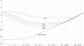
This graph shows the effects of different size filter caps on PSRR as compared with a separate supply.
I was injecting 1VAC into each rail at with a 180 phase shift between rails - this was the most challenging noise source.
My supply is already very low noise but it will be modulated by the signal so I think any mod that brings improvement here will be significant.
http://www.diyaudio.com/forums/soli...s-lateral-output-perfect-209.html#post2743197
This graph shows the effects of different size filter caps on PSRR as compared with a separate supply.
I was injecting 1VAC into each rail at with a 180 phase shift between rails - this was the most challenging noise source.
My supply is already very low noise but it will be modulated by the signal so I think any mod that brings improvement here will be significant.
Attachments
Last edited:
Thanks for that.
470uF sounds about normal.
4700uF seems like overkill and yet the sim says "big improvement".
And the sim predicts that much higher filtering RC perform better still. Enlightenment.
470uF sounds about normal.
4700uF seems like overkill and yet the sim says "big improvement".
And the sim predicts that much higher filtering RC perform better still. Enlightenment.
I guess the question is:
At what point is the noise so low that we no longer notice any benefit ?
I suspect that we're not there yet 🙂
At 100hz a separate supply give an astonishing 75dB improvement over my current 470uF
At what point is the noise so low that we no longer notice any benefit ?
I suspect that we're not there yet 🙂
At 100hz a separate supply give an astonishing 75dB improvement over my current 470uF
Last edited:
Indeed, I already did that. 🙂
One of my K-multipliers turns a 470uF cap into a 22F cap! This is what's seen by the load. The input filtering is determined by the RC filter but the upper limit seems to be 50-60db isolation in practice.
- keantoken
One of my K-multipliers turns a 470uF cap into a 22F cap! This is what's seen by the load. The input filtering is determined by the RC filter but the upper limit seems to be 50-60db isolation in practice.
- keantoken
Kean,
are you saying that when built and tested, all these variations come in around the -50dB line?
That neither -100dB, nor -75dB, can be achieved in practice?
are you saying that when built and tested, all these variations come in around the -50dB line?
That neither -100dB, nor -75dB, can be achieved in practice?
In reasonable simulations, I don't think I've seen anything over 70db. Since even Cordell's models suggest ~70db possible rejection, I'm willing to believe it can be done. But for some reason the ones I built, along with those of a friend, were between 50-60db. I suspect it is the protection diodes I use, and perhaps the diode models in SPICE are off. OR, maybe my measurements were contaminated.
EDIT: I don't know, I seem to be close to SPICE predictions, the version I use on my Fetzilla gets 67db isolation for the 120Hz ripple, at 230mV in to 100uV out. I just measured this. So I'd say it can vary between 50db-70db, and quite possibly below 60db means something is wrong.
I don't think 100db could be achieved in practice without adding extra filtering in series, because the filtering of the multiplier at all frequencies is limited by the Early effect of the transistors, irrespective of the RC network.
I have posted more advanced schematics involving an extra filter in series, but they are not so economically impressive as the K-multiplers themselves...
- keantoken
I understand that is a significant limit at the input LTP and if you have the chance to read "Self on Audio" there is a good article from EW, May 2003 there, with sims and experiments, entitled "Power Amplifier input currents and their troubles". One solution to early effect ripple induction was the cascoding of the tail with just one cheap transistor. Watch where you bias it though - the midpoint of the CCS reference earth resistor was used in the model, where a decoupling cap to the rail is also commonly fitted.I don't think 100db could be achieved in practice without adding extra filtering in series, because the filtering of the multiplier at all frequencies is limited by the Early effect of the transistors, irrespective of the RC network.
That's true. Since the input transistor is where most of the bad PSRR comes from in this amp, a cascode there may be as effective as frontend supply filtering. However then the VAS is not covered. But, we know that others have found worse SQ when moving the VAS to a different rail, so this may be the best option for both worlds.
There are many ways to fix the Early issue for the K-multipliers. However from a simplicity standpoint, I think this is the point of diminishing returns. If you need more than 60db of supply isolation that goes deep into bass, then you probably will want to customize the design to your application, and a one-size-fits-all is no longer reasonable.
- keantoken
For me I will build a separate regulated supply for the i/p & VAS stages. I think this is the best solution and perhaps later will see if I can come close matching it with other methods.
But also the secondary advantage that I can now have a few extra volts on this supply which will me especially useful if I end up using the driver devices before my o/p mosfets as these will use an extra volt or two.
But also the secondary advantage that I can now have a few extra volts on this supply which will me especially useful if I end up using the driver devices before my o/p mosfets as these will use an extra volt or two.
I just added 22,000uF across the 470uF filter cap.
I recommend this mod ( or something else that addresses this PSRR issue ).
Subjectively it helps the solidity of the bass, smoothness in the midrange and general feeling of effortlessness.
It makes it sound like a much more expensive amp 🙂
mike
I recommend this mod ( or something else that addresses this PSRR issue ).
Subjectively it helps the solidity of the bass, smoothness in the midrange and general feeling of effortlessness.
It makes it sound like a much more expensive amp 🙂
mike
The amplifier output responds to the theoretical improvement that your sim showed.
That is quite at odds with Kean's conclusion.
That is quite at odds with Kean's conclusion.
I think he was referring to a multiplier - mine's just a simple, but extreme, RC filter.
Anyway, it's so easy to check it out, took me less than 1/2 an hour.
Anyway, it's so easy to check it out, took me less than 1/2 an hour.
I thought Kean was saying that 50 to 60dB PSRR was about as good as it gets.
If instead he was saying that is a limitation that only applies for his (or similar) Multiplier then your results are showing that a simple RC filter can give better results.
If that is the case then the limited PSRR multiplier is performing less well, than an RC filter.
If instead he was saying that is a limitation that only applies for his (or similar) Multiplier then your results are showing that a simple RC filter can give better results.
If that is the case then the limited PSRR multiplier is performing less well, than an RC filter.
The best solution for this is to take a voltage doubling tap from the PSU's to get about + & - 50V and then use a good CCS / shunt regulated supply for the ip & VAS to take it back down to about + & - 30V for full DC regulation.
As my 4 x 22,000uF caps cost about 40 pounds in all the above solution may also be cheaper - but not simpler, adding the caps is about as simple as a mod can be.
I will probably design a new board for an i/p buffer and + & - regulators but for now I'm just enjoying the big caps 🙂
mike
As my 4 x 22,000uF caps cost about 40 pounds in all the above solution may also be cheaper - but not simpler, adding the caps is about as simple as a mod can be.
I will probably design a new board for an i/p buffer and + & - regulators but for now I'm just enjoying the big caps 🙂
mike
- Status
- Not open for further replies.
- Home
- Amplifiers
- Solid State
- JFET input, MOSFET VAS, LATERAL output = Perfect!!