Andrew,
I'm beginning to suspect that increasing the size of the interstage filter caps, or rather adding another much larger one, would yeald better results that just adding more capacitance to the o/p stage PSU.
If we keep the feedback device current really clean that in turn will improve PSRR and looking at it another way . . . any noise in the i/p device is amplified about 20 x so reducing noise their pays a premium
it may be that your small series chokes will be enough but I would still recommend common mode chokes.
Last edited:
I read here that the RC time constants of the passive input filter and the NFB DC blocking filter and the PSU filter have to be in a crictical ratio to work effectively and avoid LF instability.
1.) PSU filter C in Farads * Speaker impedance in ohms >= sqrt(2) * NFB filter C * Lower leg R.
2.) NFB filter R*C >= sqrt(2) * Rin * input DC blocking filter.
Your increasing of the NFB CR is using the second of those "rules".
I have been doing this for quite a few years now and for me it clearly improves LF performance. The really nice bit is once these CR ratios are setup/built in, it is very easy to reduce the passive input CR to hear the effect of early bass roll-off without contravening those rules.
I should remind you Andrew unless I say otherwise my comments refer to my DC linked version. My PSU cap is 33mF and at present my filter caps are 470uF.
Supply rail filtering is different from amplifier gain filtering.
However, the four uF caps shown will all have an effect on bass performance.
Each must filter the modulation on the supply rails to a low enough value to be inaudible at the output for whatever range of signals you pass through.
I would expect variations in audio performance when any of those caps is made too low in value that the rail modulation leaks through to the output.
yes, I agree and I will try a much bigger filter cap soon and assess it's subjective effect.
But spice indicates that no practical amount of capacitance can ever give as good a result as a separate supply so that will be the next thing I do.
But spice indicates that no practical amount of capacitance can ever give as good a result as a separate supply so that will be the next thing I do.
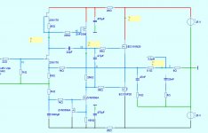
After some more research this diagram shows what I will be working towards over the next few weeks.
Both the i/p buffer and the o/p transistor "pairs" give better stability which means the amps should sound clean & smooth with less compensation.
But I am hoping for the biggest improvement from the separate supplies which give enormous gains in PSRR in the 100 - 1000 hz range.
Very soon I will be listening on my new IPL transmission line speakers which I'm just constructing 🙂
http://www.iplacoustics.co.uk/S3tl Rib CP.htm
Attachments
Nice! I've been thinking amplifier pulse behavior depends way too much on the input impedance, so I think an input buffer is a really good idea, if you want to fine tune stability, and possibly the sonics as well.
- keantoken
- keantoken
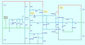
yeah, as I mentioned already, when I reduced the i/p series R to 20 the sonics improved significantly but an i/p filter was not possible. With the buffer I hope to get the advantages of both. The supply to it will probably be a bit better than shown.
why not use the B-1 N channel buffer so you avoid the endangered P-channel species...conservation and preservation makes sense....🙂)
Hi Michael,
Thx for the idea, till now I have not heard of the B-1 N channel buffer but I will check it out.
I would want to somehow loose those caps though - I want to see just how good I can get the DC linked version to sound before I try other design philosophies.
I do have some N & P channels for now so why not use them !
Hi Michael,
Thx for the idea, till now I have not heard of the B-1 N channel buffer but I will check it out.
I would want to somehow loose those caps though - I want to see just how good I can get the DC linked version to sound before I try other design philosophies.
I do have some N & P channels for now so why not use them !
Then you would want the Symmetrical B1 Buffer ------------------------------ http://www.diyaudio.com/forums/pass-labs/145201-building-symmetrical-psu-b1-buffer.html#post1854512
Mikelm,
Have you considered a jfet/bjt cfp as input, some good advantages. The drivers on the laterals is excellent idea.
Have you considered a jfet/bjt cfp as input, some good advantages. The drivers on the laterals is excellent idea.
The cfp is more linear and cfp by principle in singleton mode favours second harmonics, less current fluctuations your gain would increase so lower distortion is possible or you could lower this with more degeneration on the vas. You can also tune the harmonic spectrum via the collector cfp resistor. The current source on the input wouldnt be needed to clean up the bass, I cant remember now if it was you that mentioned the amp sounds muddled in the bass with complex music, thats the result of having very high second order distortion, it is only good for simple music.
When I added the i/p stage CCS it did sound much cleaner ( but I did not mention bass ) but I did not establish yet if that was principally due to lower HD or lower noise. When I add a separate supply for the i/p & VAS stages that question should be answered.
My VAS is constant current therefore degeneration has no effect.
thanks for the suggestion - I will try it.
mike
My VAS is constant current therefore degeneration has no effect.
thanks for the suggestion - I will try it.
mike
Another variation you might like to experiment with is using a mosfet beta enhancer followed by folded cascode bjt as vas. Its the last version I experimented with after I got interested in this type of design mainly due to the renardson MJR design. It was excellent at voices.
- Status
- Not open for further replies.
- Home
- Amplifiers
- Solid State
- JFET input, MOSFET VAS, LATERAL output = Perfect!!