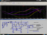
Please see below the circuit I've been listening to for the last few days.
I have made 4 significant changes over what I regard as the "Vanilla" version of the DC linked design.
4) Put 3310a's in front of O/P devices to create MF "darlingtons"
( the diagram show 3306's but that actual amp has 3310's throughout. )mike
 Nice, and You did with fets, speed is increased also...
 Mike,
The danger with CFPs is always the switching behaviour. The best outcome is ringing, the worst, oscillation at the crossover. The former is OK with this amp if you control the speed with a gate/drain cap on the CFP driver since the inactive side will only switch when the output passes about 5-8 volts peak.
I believe the reason this amp is easy to stabilise is because of very low transconductance in first and output stages, leading to low loop gain, around 50dB. If you use a CFP in the output stage, the transconductance will be completely swamped by the constant current driver, raising loop gain by several dB, possibly as much as 10dB. In turn this will require adjustments to compensation, and this will actually change the sound, making it arguably more transparent, less 'rounded', and more like a SS bipolar device amp.
One of the charms of this design is this low loop gain; a low feedback amp does sound palpably different to a high feedback design; transparency and 'atmospherics' are demonstrably NOT at the same end of the spectrum!
Removal of the bias gen cap will introduce some distortion due to small variations in VAS current, leading to shifting bias points. This will likely be even order, however, and pleasing to the ear.
Great work, thanks Mike,
Hugh
Last edited:
Removing the bias spreader cap will turn the bias spreader into a gate stopper for the lower FET, though this may not matter much because of the darlingtons now.
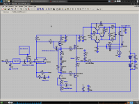
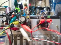
I just built this and am listening to my Fetzilla using it to filter the positive rails. It is a high-current version of one of my K-multipliers, HIGHLY experimental. So far I have 50MHz oscillation, though I'm not sure where from... But that's actually not bad, compared to the worst case scenario of it dumping lots of amps into the output capacitors and blowing stuff up. No, it doesn't store power, but it will replace a capacitor bigger than your head for filtering purposes. It is not a simple as it looks...
ROYG traces are PSRR, purple traces are output impedance.
- keantoken
Attachments
Well, the oscillation wasn't the amp OR the K-multiplier, because it is still present when the circuit is off. It must be interference. Sometimes I suspect my oscilloscope is oscillating. 🙁
The K-multiplier lives up to it's simulations in this case. There is a ripple peak I think is caused by the capacitor charge pulses on the negative/unfiltered rail, but aside from that, I have not seen ripple during play go above 5mV peak. Though I am using sensitive FRs in a small room.
The bass definitely seems more authoritative and interfered with other instruments less, and this carries up into the midrange, making for some nice, clean guitar. However some of the treble clarity is missing, so I suspect I need to re-tune compensation. One more thing I may have difficulty doing without a signal generator.
- keantoken
It's true that a signal generator and scope are handy when playing with compensation but ultimately it's our ears that have to decide what value we prefer.
Without a signal generator, you can cut out one step and just go by ear and if your scope allows, check to make sure it's not oscillating.
Otherwise, perhaps you could use a battery, switch and pot to create a step response. That should work if you can get the scope to trigger with the step and it should give you a nice fast & straight leading edge.
mike
Last edited:
I think realistically, you will need a pulse, square wave or AW generator, if only for the repetitive forms allowing on-the-fly adjustment. The chances of arbitrary switch bounce etc. probably make observations a bit hard with one-shots unless they are logic controlled or such.
It's not hard to build simple, very sharp edged pulse and squarewave generators that work reliably up to the MHz region. A couple of monostables and hex. buffers are enough for real quality at audio frequencies. A simple stripboard assembly, battery or bench supply is fine.
Though there are plenty of cheap used generators out there, the really old ones tend to be a bit slow or ring as bad as the DUTs. Check first.
Last edited:
Different o/p devices & OLG
Hi Hugh,
I did some spice work on this topic after your comments got me thinking about this.
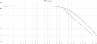
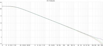
As you can see below the OLG in the audio band and up to about 100Khz, with no compensation, is substantially the same for single MF o/p device ( red ), darlington o/p MF ( green ), and MF CFP o/p ( blue ). Above 100khz both the darlingtons & CFPs show similar increase in OLG - up to about 20db more.
However, when 33pF of lag compensation is applied, the three different o/p options show very little difference in the critical regions - only about 2db difference between them.
But, the MF darlingtons give a considerable phase margin advantage and the CFPs appear to give even more.
Provided, as you suggest, the MF CFPs are less susceptible to ringing / oscillation than the bipolar version, then I think they could be a good sounding o/p option for this design.
As you can see from the graphs I have already defected to the "high feedback" school of thinking by using a CCS in my i/p but as long as this is suitably curtailed before critical region I find no disadvantages and many advantages - because, so long as we employ about 33pF of lag compensation, the OLG in the critical region is more or less the same with this design regardless of whether we use an i/p CCS and regardless of which of these o/p options is chosen.
This has encouraged me to add the CFP o/p to my list of things to try. 🙂
I believe the reason this amp is easy to stabilise is because of very low transconductance in first and output stages, leading to low loop gain, around 50dB. If you use a CFP in the output stage, the transconductance will be completely swamped by the constant current driver, raising loop gain by several dB, possibly as much as 10dB. In turn this will require adjustments to compensation, and this will actually change the sound, making it arguably more transparent, less 'rounded', and more like a SS bipolar device amp.
One of the charms of this design is this low loop gain; a low feedback amp does sound palpably different to a high feedback design; transparency and 'atmospherics' are demonstrably NOT at the same end of the spectrum!
Hi Hugh,
I did some spice work on this topic after your comments got me thinking about this.
As you can see below the OLG in the audio band and up to about 100Khz, with no compensation, is substantially the same for single MF o/p device ( red ), darlington o/p MF ( green ), and MF CFP o/p ( blue ). Above 100khz both the darlingtons & CFPs show similar increase in OLG - up to about 20db more.
However, when 33pF of lag compensation is applied, the three different o/p options show very little difference in the critical regions - only about 2db difference between them.
But, the MF darlingtons give a considerable phase margin advantage and the CFPs appear to give even more.
Provided, as you suggest, the MF CFPs are less susceptible to ringing / oscillation than the bipolar version, then I think they could be a good sounding o/p option for this design.
As you can see from the graphs I have already defected to the "high feedback" school of thinking by using a CCS in my i/p but as long as this is suitably curtailed before critical region I find no disadvantages and many advantages - because, so long as we employ about 33pF of lag compensation, the OLG in the critical region is more or less the same with this design regardless of whether we use an i/p CCS and regardless of which of these o/p options is chosen.
This has encouraged me to add the CFP o/p to my list of things to try. 🙂
Attachments
Last edited:

Maybe this one but with 2sk170 lineup front end schematic ?
2sk170 with 2 CSS look like AlephP1.7
Today after connecting the high-current K-multiplier I disconnected the frontend rail filter. There was an increased clarity in the treble and midrange. Since the rail variations are below 5mV, I don't think it is necessary. I will next adjust the convenient trimmer cap I have placed as the phase lag compensation to try and dial in the enjoyable sound again... Unfortunately this does not necessarily coincide with a stable amplifier.
- keantoken
- keantoken
Ahh - ok, we have chosen different approaches.
I am thinking now to just have some simple choke regulation on the o/p + & - 25V supply, use some diodes & caps to make a voltage doubler to give me + & - 50V and then regulate this down to a very clean + & - 35V for the i/p & VAS.
It would be great if we all had enough time to try every option !
For me, I think to achieve that enjoyable lively sound we have to ask all elements in the audio chain to participate.
With a fairly lively DAC & speakers I find 33pF of lag compensation can sound very nice but with different speakers or DAC I have heard it sound as dull as dish water.
cheers
mike
One of the advantages provided by the K-multiplier over a passive supply is that you can have 10mR output impedance at 1Hz and 60db input rejection at 10Hz - however much it matters. Wiring impedance could easily be over 10mR to the outputs, but a low regulator impedance means it contributes less total distortion to the rails. I tried to design the regulator to be stable into all caps, film or otherwise, and so far it hasn't oscillated into the 1uF film bypasses I have. I think this is a key feature of regulator design, because no good regulator can shorten a long trace...
- keantoken
- keantoken
Say.. would you believe a sub-ppm (0.000084%) 20KHz 150 Watts into 4-OHm all-FET amp? A minor cheat though, the current sources, 3 of 'em are still ideal sources.
It is amazing what a perfect CCS can do. If we could see a schematic we could go about finding caveats.
Actually this happens a lot, someone goes into a random thread and says "hey, have you seen an amp with <.0001% THD?" and then proceeds to inform us all about his simulations... I suspect simulation gives us a sort of rush... Like gambling. There are many such simulations, and perhaps many of them would live up to simulation if they were built by an expert in real life. Unfortunately designing the lowest-THD amplifier doesn't give much reward for the cost incurred, aside from bragging rights, which is why I am more interested in what sounds good for the moment.
- keantoken
Yeah, I noticed recently that if you put a crossover & two simulated drivers instead of just 8R then the THD Fourier results take a real dive - perhaps to realistic values.
great, the simulator is predicting what happens when the model changes............. put a crossover & two simulated drivers instead of just 8R then the THD Fourier results take a real dive - perhaps to realistic values.
Well, it's not all that shocking, when made with actual models distortion degeneration should be in the same ballpark as the overal amp THD.It is amazing what a perfect CCS can do. If we could see a schematic we could go about finding caveats.
Here I sense you're getting offensive. I did nothing more than to state THD figures for an all-FET amp. Surely, getting a low THD is like a sport but the primary goal is still to design an amp that listens good besides measuring good.Actually this happens a lot, someone goes into a random thread and says "hey, have you seen an amp with <.0001% THD?" and then proceeds to inform us all about his simulations... I suspect simulation gives us a sort of rush... Like gambling.
Here it becomes more obvious what you're trying to do, which is trying to demean the performance statement I made. I'll have to take away those assumptions for you: I both sim and build my designs. Funnily enough, real-world results are better than what I get in the same. That should promise something for the design I posted about in this thread.There are many such simulations, and perhaps many of them would live up to simulation if they were built by an expert in real life.
I referred to this before by saying yes, the primary goal is to get an amp that sounds well. But why can't it sound well and also measure extremely well?Unfortunately designing the lowest-THD amplifier doesn't give much reward for the cost incurred, aside from bragging rights, which is why I am more interested in what sounds good for the moment.
Look, I posted in this thread not randomly, but because the design fits the topic title: it's an all-FET, JFET input design. And no, parts won't cost you an arm and leg and no, there aren't an enormous amount of parts either 😉
Maybe, if we could be a little less hostile 😉If we could see a schematic we could go about finding caveats.
Well, sounding good and having low THD is a desirable combination for sure. But you didn't mention it was supposed to sound good too. Forgive me for not making that assumption. I am jaded; I must work on that.
I would be glad to discuss your design, regardless of how I may seem. You should accept that it really is believable to see such low THD numbers coming from simulation. As for real life, anything is believable too. Let's find out.
- keantoken
I would be glad to discuss your design, regardless of how I may seem. You should accept that it really is believable to see such low THD numbers coming from simulation. As for real life, anything is believable too. Let's find out.
- keantoken
- Status
- Not open for further replies.
- Home
- Amplifiers
- Solid State
- JFET input, MOSFET VAS, LATERAL output = Perfect!!