Some extra info if it helps, I measure 30v after bridge rectifier. Using 3.9v 0.5w zeners, 5 pieces as suggested.
I have seen previous post in this thread from use Robertor with same problem but didn't see an answer on that one.
Any other points I can check?
I have seen previous post in this thread from use Robertor with same problem but didn't see an answer on that one.
Any other points I can check?
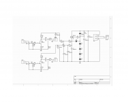
thare are not marked test points on schm and I can't decipher from pcbs what's in case
anyway - triple check values of all zeners , their orientation on pcb , same as resistor values
across each zenner diode (D2-D5) there must be 4V
what's that value 4V ??? 3V9 is standard ..... and that difference is irrelevant
there must be around 16V at Q1 gate , so around 12V a t drain , going to audio circuit
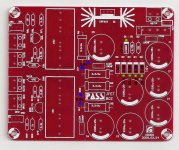
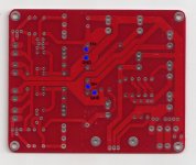
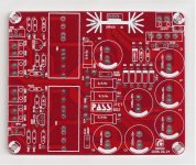
Here you have good view of the PCB, still need to find out the 16+ point on the schematic. Edit; if I look correct one +16 is between r6 and r4
Did some measurement. The zeners read a little less than 4volts. I measured between green points also between D1-D2 etc. I can see it sums up from D1 17.17 to 29.7 D5.
Only thing I don't understand why it is 8.9v at the checking points. Must find out it I need to use less or more zeners.
Sorry I have no background in electronics. Thanks for any help.
Attachments
Last edited:
check zener string to have 16V across (thats also voltage across C7), then you'll have 12V at mosfet's drain
current through zeners is OK , but they are off value
you can also just add one more ( of those shitty ones) in series
you can combine different values of zeners , as long you get 16 to 16V5 as final voltage across them
current through zeners is OK , but they are off value
you can also just add one more ( of those shitty ones) in series
you can combine different values of zeners , as long you get 16 to 16V5 as final voltage across them
Are you sure the correct value zeners are used?
You're getting about 12.8V across the zeners Z2 to Z5. Subtract the Vgs of the Q1 (~4V) and the 8.9V C2 voltage is reasonable.
My guess is that if your goal is to get around 16V to the jfet circuitry then you need
to change the zeners to sum up to closer to 20V. And you may want to decrease
R1 to make sure the zeners have enough current to give a stable voltage.
Cheers,
Dennis
Edit: It looks like the great ZM has already answered.
Thanks alot Zen Mod and Dennis!!
I am going to get some different valued zeners (hopefully not the same **** ones) and try to get the 16v reading across C7.
I am going to get some different valued zeners (hopefully not the same **** ones) and try to get the 16v reading across C7.
Last edited:
Hi Parap,
If you are unsure about the value of the zener (perhaps they have been mislabelled in your parts store),
you can test them out before installing them. Please see part about testing zener with a volt/multimeter
section in the link below. You need just a resistor and a 9V battery.
How to Test a Zener Diode
Cheers,
Dennis
I have never measures volt on zeners so thanks for the link Dennis. I think I will go for the 16volt to R7 mark as suggested by Nelson. So you are right I probably need 20v zener string D2-D5 and change R1 to 1,5K ohm.
Woody, good that you noticed. I will change C1 as well!
Woody, good that you noticed. I will change C1 as well!
Gain and distortion of J110/2SK170BL BOZ-J
I am currently using a choke loaded BUZ900P MOSFET follower output stage with choke-loaded 6E5P tube linestage and getting very good results . It would be nice to try an all-SS setup which I have not used since the early 1990's
Would a BOZ-J be suitable in place of the 6E5P linestage ? I need approx. gain of 10 or more and around 10VRMS maximum and wondering what sort of performance a BOZ-J would offer . I can't seem to find specs on the thread with regards to distortion . I have 2SK170BL and J110 available .
cheers
316a
nope
JFet BOZ is too sissy for 10Vrms and gain of 10
what you need ..... is completely different
even if starting from JFet BOZ , you need added cascode , increased loading resistor and increased PSU voltage , to achieve both voltage swing and gain
JFet BOZ is too sissy for 10Vrms and gain of 10
what you need ..... is completely different
even if starting from JFet BOZ , you need added cascode , increased loading resistor and increased PSU voltage , to achieve both voltage swing and gain
Last edited:
Thanks for the responses . I should have looked at the datasheets first . I forgot what puny devices some of these little three legged fuses can be 🙂
The cascode version sounds interesting .
cheers
316a
The cascode version sounds interesting .
cheers
316a
What is your measured Idss and Vp? Without those 2 numbers, nobody can give you meaningful answer. There is a wide value spread.best resistor values fr a BOZ for J310 or J309 ?
needing low gain and low z out
- Home
- Amplifiers
- Pass Labs
- Jfet BOZ