If you confine yourself to Sallen-Key crossover filters, a unity gain buffer is all you need, and there are many, many ways to skin that particular cat. I showed a few of them in this thread. My point is that many yakk, many quibble, but few do. I don't care how you do it, really. Even a decent opamp-based active crossover will make at least discernible, if not beneficial changes to the system. If you don't try it, you'll never know. There won't be any kits from my end, as I don't have the time or the inclination to provide the support. If a kit is all you can handle, buy someone else's kit and learn from the effort, then mod it if you desire, as you gain understanding. The circuits here are all constructed from simple building blocks, relatively easy to understand if you take the time to break down the circuits into their fundamentals. I use jfets and mosfets because that's been the thrust of my research over the past four years, starting with RIAA preamps and lineamps, and finally crossovers. I haven't felt the need or the desire to so much as touch an opamp in all that time (with one diversion/exception).
I have enough amps lying about (and more coming) so that it's not a big chore to biamp now that I finally have the crossover for the job. Right now, I'm working with my "Shrine" tube amp and "Gain Clown" composite gainclone, both documented on this site. When I get around to it, I'll push the clown aside and replace him with one of my other tube amps. "Amp rolling" will be fun for a while.
Once I build my tube preamp, a hybrid tube/mosfet crossover will eventually follow. Don't hold your breath for that, though - my project queue is really long.
Hi,
even when You look at high-end-money-is-no-object products You´ll find that most of those were designed with the "red pen" in mind, or which are just copies of standard application notes and that the price tag is rather due to casing design, image of the company and marketing. Sound seems to be hardly a factor in the design of most audio gear.
Who are the companies offering service in form of application notes, design notes and other design assistants?? It are the IC-manufacturers. Who have not much interest in the comparably tiny HighEnd market. They don´t have official interest in measurement procedures that prove their products might be flawed. See for example whats going on with the newer National Semi´s hyped OPamps. Of the first 22 pages of the Datasheet of the so claimed "high performance, HiFi Audio OP" LM4562 17(!!) pages are containing numerous THD-diagrams, which is useless information regarding audio-qualities. What´s left could have been shown on just 1 page. On the other hand are some useful diagrams missing. Probabely because they would show the OP to be rather mediocre and anything but an audio amplifier. Still though the highend community raves about the chip and its low THD-figures.
Simple discrete designs hardly win prices when measured with standard THD-measurements. But customers have been brainwashed so heavily that they still want to know those THD-numbers and decide by those numbers rather than trusting their own ears and common sense.
So, if I had to design on a budget, I´d very probabely search if a fitting design has been done already and proven to be functional and reliable. I´d find such in a application note or evaluation board together with layout recommendations and possibly even gerber files and BOM. The effort, time and cost of design could be considerably reduced. Just for good looks and marketing I´d put some highly regarded boutique parts at strategic points where any tester will put the lens on. I´d check if that design fulfills my certain requirements and has low enough numbers to please customers, magazines and marketing flyers. If my company has a good reputation and/or a well equipped ads-budget I know that test and consumer response will be positive. I´d send the data to a lowcost supplier, probabely in the far east and after 2 weeks the postman rings my doorbell and I can start selling. Voila....why should I spent time thinking of a truely own discrete design, which takes more time, cost, customer convincing and overall effort when my competitors do the same as I? Situation could change the moment when customers knew how much better sound could be reproduced and trusted in their ears and not in numbers, tests and marketing blabla.
Anyway, as some fellows already recommended. Test it yourself. If You´re lucky You might even simply replace socketed OPamps by a discrete, global feedback free buffer (JFETs recommended).
jauu
Calvin
if you confine yourself to Sallen & Key unity gain crossover filters, a unity gain buffer is all you need.If you confine yourself to Sallen-Key crossover filters, a unity gain buffer is all you need,
If you choose to use the Equal Component Value version of S&K filters then you must use a gain block inside the feedback loop.
The gain of the gain block is then independently available to adjust the Q of the ECV S&K filter without altering the frequency of the filter.
That is the big disadvantage of the unity gain S&K, the frequency and Q are dependent on each other and the gain can only be ~ 1times. (sometimes this gain of 1times is a big advantage).
For more complete independence of; Gain & Q & F there is the MFB active filter
For a plain vanilla Linkwitz-Riley crossover, unity gain buffers are fine. I may wrestle with options that require gain (much) later.
If you confine yourself to Sallen-Key crossover filters, a unity gain buffer is all you need, and there are many, many ways to skin that particular cat. I showed a few of them in this thread. My point is that many yakk, many quibble, but few do. I don't care how you do it, really. Even a decent opamp-based active crossover will make at least discernible, if not beneficial changes to the system. If you don't try it, you'll never know. There won't be any kits from my end, as I don't have the time or the inclination to provide the support. If a kit is all you can handle, buy someone else's kit and learn from the effort, then mod it if you desire, as you gain understanding. The circuits here are all constructed from simple building blocks, relatively easy to understand if you take the time to break down the circuits into their fundamentals. I use jfets and mosfets because that's been the thrust of my research over the past four years, starting with RIAA preamps and lineamps, and finally crossovers. I haven't felt the need or the desire to so much as touch an opamp in all that time (with one diversion/exception).
I have enough amps lying about (and more coming) so that it's not a big chore to biamp now that I finally have the crossover for the job. Right now, I'm working with my "Shrine" tube amp and "Gain Clown" composite gainclone, both documented on this site. When I get around to it, I'll push the clown aside and replace him with one of my other tube amps. "Amp rolling" will be fun for a while.
Once I build my tube preamp, a hybrid tube/mosfet crossover will eventually follow. Don't hold your breath for that, though - my project queue is really long.
Thank you for your help.
Yes, at this point in my electronics infancy a kit is all I can handle. I didn't intend to ask you to do a kit, wrenchone, but if you happen to know who does I would be most grateful for that information.
Regards,
Just discovered this thread, but this is exactly how I built my xovers
I used the same idea (FET buffer used in unity-gain Sallen-Key filters) to build my current active crossovers, and it was a HUGE improvement over the previous op amp-based versions. The xover point is pretty low (70Hz, 2-way) and this configuration seems amazingly transparent through the mids.
I deliberately set the gain structure of the output buffers so that the only volume control is on the LF side, so that the high-pass just goes through a FET buffer straight to the output. The low-pass side has a volume pot feeding a 797-based output stage with gain.
Peter
hi,
I would like to see a diagram of your circuit if you could put one up, and Is it possible to make a variable jfet crossover filter?
Jfet opamps better for audio than standard ones?
I am new to jfets and still reading!
Thanks to all that contribute here!
I would like to see a diagram of your circuit if you could put one up, and Is it possible to make a variable jfet crossover filter?
Jfet opamps better for audio than standard ones?
I am new to jfets and still reading!
Thanks to all that contribute here!
There's a diagram of the circuit I'm currently using at the beginning of this thread - it will do as a starter. The board shown near the end of the thread hasn't been put into a case yet.
It's possible to make a variable frequency filter using dual pots/switched resistor networks that have the necessary accuracy and tracking, though that's outside the scope of this thread. Opamps are not germane here as well - this is a thread regarding discrete jfet crossover filters. A search will give you multiple threads (too many, really) about the relative virtues of this or that opamp.
It's possible to make a variable frequency filter using dual pots/switched resistor networks that have the necessary accuracy and tracking, though that's outside the scope of this thread. Opamps are not germane here as well - this is a thread regarding discrete jfet crossover filters. A search will give you multiple threads (too many, really) about the relative virtues of this or that opamp.
Hi,
though I like JFET-OPamps more than bipolars, they are still OPamps and designed like typical OPamps. Btw, what -apart from marketing blabla- could qualify a OPamp as ´audio´-OP? Apart from Noise-figures probabely nothing! OPs feature tons of openloop-gain, very small openloop bandwidth, low bias-currents, rather more integrators than anything else and surely no amplifiers and no design goals used for good sounding audio gear.
The trend towards ever lower supply voltages and lower current consumption doesn´t improve matters. If a circuit needs to be linear and fast, class-A and loads of current are still unbeatable.
Most so called JFET-OPs use a JFET-Input stage only and bipolar transistors for the rest of the circuitry.
Basically the only advantage of such OPs against bipolar OPs is, that they show lower offsets because of their extremely small input bias currents, which means an advantage whith high and greatly varying source impedances. Such varying impedances typically occur in filter circuits (the caps). Noisewise JFET-OPs are on par or better than bipolar OPs with source impedances of a few kOhms and up.
jauu
Calvin
I've been doing a lot of listening to my first active crossover circuit in conjunction with a new RIAA preamp/line amp, and some newly constructed Parts Express "Tritrix" speakers built using the recession buster kit that includes the drivers, crossover components, and knock-down MDF cabinets. The crossover components are still in the box, as these speakers were modified so that I could bi-amp them.
They started out as hot needles through the ears unlistenable, especially on stuff like piano. I did a little research and noticed that not only did the 51/4" mid-woofs have a nasty peak at around 5kHz, but that the crossover components supplied with the kit dictate a crossover frequency of ~1.5kHz. I lowered my crossover point to 1.5kHz, and voila! - the speakers became more listenable. I've been listening to this combination for a few weeks, but I'm still not satisfied. The sound is kinda hot and forward, and the pins and needles return pretty much full force at high volume. Having said that, there's a lot of musical detail present that would be nice if the speakers weren't trying to shred my ears.
I suspect that two factors are at work here. First is that that 5kHz peak in the drivers is still there and getting excited at high volume. Second, it's just two 5 1/4" drivers trying to process all the low/mid frequency detail, so I suspect that doppler distortion is also rearing its ugly head a bit.
Forward into the past! Before I assembled the TriTrix speakers I was using a pair of speakers I put together back in 1979. These are hexagonal prisms loaded with (16) pieces of a JBL/Vifa driver that was offered at Parts Express a few years ago. They previously used some Westwell drivers I got from McGee Radio for 5 bucks each. The Vifa/JBL drivers are 4 ohms, so the speakers a 4 ohms, with 4 series strings of four drivers each connected in parallel, along with 3 ancient Vifa fabric dome tweeters. The JBL/ Vifa drivers start to have a few problems at higher frequency, starting with a pretty high amplitude notch at 6kHz, and some peaks and valleys thereafter, though none are as severe as the 5kHz peak exhibited by the Dayton drivers in the Tritrix. I never was terribly happy with the 4 ohm impedance, either. These speakers were also rough at high volume. They were crossed over at 5kHz with an external passive filter in deference to the Vifa tweeters.
Anyway, I shifted my main amp to the 4 ohm tap, and connected up the old speakers to the biamped system with the 1.5kHz crossover point. These speakers are now much smoother and listenable at high volumes, and sail through crescendos that made me grit my teeth before. I suspect the tweeters aren't liking the 1.5 kHz crossover point all that much, but I have some Peerless DT100 tweeters I can substitute that will like it just fine. Meanwhile, I can look at cone treatments or driver substitutions that can tame the nastiness of the Tritrix speakers. I have a couple of candidate drivers in mind from Peerless and Tang Band, if they only made them in 4 ohms as well as 8.
Hi,
I could recommend the Vifa 17WN225-8. Its quite an underdog, beeing Vifa´s oldest 6.5" driver and still one of their best and one of the cheapest at the same, featuring an aluminium basket. It runs silky smooth without any tendency of peaking and a smooth rolloff. Just a simple inductance is needed for Xover frequencies of up to 3kHz, rather to control dispersion than shaping the amplitude response. It pairs well with Vifa´s XT ring-shape radiators. The 17W225 features good efficiency, especially when paired in a symmetrical MTM-design. As satellite in a small CB or BR (placed close to a wall) it could easily be driven by a fine tube amp delivering just about 10W of power.
See: http://www.diyaudio.com/forums/multi-way/125902-hi-end-sealed-mtm-bookshelf-design-2.html for reference.
jauu
Calvin
Hi Wrenchone
I've read through this thread with close interest a couple of times. I'm planning some experiments, I was wondering if you had anything to add after you had a chance to put your active filters into your system?
Thanks
Steve
I've read through this thread with close interest a couple of times. I'm planning some experiments, I was wondering if you had anything to add after you had a chance to put your active filters into your system?
Thanks
Steve
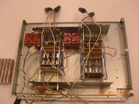
Hello all,
i have posted this in another thread as well. I use a prototype of a PLLXO with discrete buffers (B1) in a symmetric setup. This works very well. Sound is astonishing. This one is battery powered.
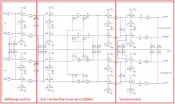
I am now building a high quality pre amp. There will be a jfet based line stage, a 46 stepped attenuator. and a integrated crossover. Complete symmetrical setup, 4 PSU included. The new cross over also has an incorperated shelving filter
The components in the divider stages and de baffle step (shelving filter) are kp1830. The coupling caps are russion PIO or silver mica (still have to experimanet with that). The filters are variable and can be set with jumpers.
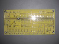
I had some PCB's made by PCB express for the crossover and now i am soldering all components to the boards.
I have shunt stepped (12 steps) attenuators on the LP and HP. Probably one only needs an attenuator on the HP section. The attenuators are not in the signal path.
regards,
i have posted this in another thread as well. I use a prototype of a PLLXO with discrete buffers (B1) in a symmetric setup. This works very well. Sound is astonishing. This one is battery powered.
I am now building a high quality pre amp. There will be a jfet based line stage, a 46 stepped attenuator. and a integrated crossover. Complete symmetrical setup, 4 PSU included. The new cross over also has an incorperated shelving filter
The components in the divider stages and de baffle step (shelving filter) are kp1830. The coupling caps are russion PIO or silver mica (still have to experimanet with that). The filters are variable and can be set with jumpers.
I had some PCB's made by PCB express for the crossover and now i am soldering all components to the boards.
I have shunt stepped (12 steps) attenuators on the LP and HP. Probably one only needs an attenuator on the HP section. The attenuators are not in the signal path.
regards,
Attachments
That's a fair amount of money invested in 2SK170s. I found that you don't even have to get that fancy in order to get good sound. My current crossover setup uses a similar buffer scheme, but with the PN4393 instead of the 2SK170. It gave my old speakers a new lease on life, merely by crossing them over at the right frequency and removing the intervening components between the amp and the drivers.
I have a "super buffer" crossover board (detailed earlier in this thread) that is sitting around waiting for me to integrate it in my preamp box. I may have to machine some air vents into the lid of my premp box, as the filter module is a bit of a current hog.
I have a "super buffer" crossover board (detailed earlier in this thread) that is sitting around waiting for me to integrate it in my preamp box. I may have to machine some air vents into the lid of my premp box, as the filter module is a bit of a current hog.
BTW, it's nice seeing someone taking the bull by the horns and putting circuits together on perf board. The modular nature of the crossover filters described in this thread makes this approach pretty straightforward. Perf-board circuits, if done with some care, are just as nice as ones done on printed circuit boards, and will last just as long. That same care in construction will yield lower parasitic capacitance than one would get from printed circuit construction.
Hi Harold,
If the filters were to be altered to 150Hz, the caps would just be scaled up to 200nF and 20nF (or 240nF & 24nF for 120Hz), without changing the resistors, yes?
If the filters were to be altered to 150Hz, the caps would just be scaled up to 200nF and 20nF (or 240nF & 24nF for 120Hz), without changing the resistors, yes?
I'm putting together this type of filter, initially for my subwoofer, using the SK filters from the first post, but using dual rails and matched jfets, a la DC coupled B1 buffer and Harolda (above).
I bought 250 2SK170 from Mouser and measured the idss so I can match pairs. The numbers are plotted in the attachment, as you can see the distribution is smooth.
Taking this data, I then set as a criterion that the idss's should be within 0.1 mA to be counted as a match. I then took random subsets of the full data to see how many pairs I could make.
250 devices: 123 pairs
100 devices: 46 pairs
50 devices: 20 pairs
Of course the non-matchable jfets can be used in plenty of other places.
I hope this data is useful to someone trying to decide between buying a bag of jfets or buying matched pairs of jfets.
Attachments
Hi Harold,
If the filters were to be altered to 150Hz, the caps would just be scaled up to 200nF and 20nF (or 240nF & 24nF for 120Hz), without changing the resistors, yes?
Dear James,
I only change the caps and keep the resistors constant, to keep the impedances right.
regards,
Harold
- Status
- Not open for further replies.
- Home
- Source & Line
- Analog Line Level
- JFET Active Crossover