Apologies. I flat out didn't see R119 - I saw a wire... Got to get to bed earlier.
With R119 it should work just fine.
Regards and apologies, Allen
With R119 it should work just fine.
Regards and apologies, Allen
You gave me a WTF moment there, looking for errors in the schematic. The circuit not only should work ok, it does, as it's in a box in my living room at this moment. Still, it's not anything I'd duplicate these days. I have much better stuff both working and in process. As I said, when I can assemble the scattered bits of my findings in one place, it'd be nice to start a thread on fancy-pants discrete shunt regulators.
So, is anyone else viewing this thread building a discrete active crossover? It's not that hard, and Vero/perf-board circuits work just as well as nice printed circuit boards with a little care. I've decided I'll need to upgrade my speakers before I near any more improvement from my electronics.
Yes, for next years project. Still have a few others to finish and am thinking I'll dial it in with DCXs and then transfer it over to the discrete stages. I'm using similar JFET buffers in my control unit now.So, is anyone else viewing this thread building a discrete active crossover?
Vero is fine and likely how I'd do it unless I did a universal board for individual filter sections and daisy chain.It's not that hard, and Vero/perf-board circuits work just as well as nice printed circuit boards with a little care.
So, is anyone else viewing this thread building a discrete active crossover? It's not that hard, and Vero/perf-board circuits work just as well as nice printed circuit boards with a little care. I've decided I'll need to upgrade my speakers before I near any more improvement from my electronics.
I'd love to. I am reading this because I searched DIYAudio for "jfet active crossover."
Problem is, I'm no electronics engineer, but a hobbyist, and I kind of need it served up on a plate. I can build to a schematic, but if there's more than the simplest of problems with a component, or setting up issues, I am simply lost at analysing it.
Now, if you were to make a kit, or print a PCB, I'd be more than interested. I think that a lot of other people on here would be too. It's the sort of thing that people are aware will produce quite an un-subtle leap in their system, but it's also quite a big step to take for most, and until somebody does a lovely gold plated board of a nice, thoroughly tested, quiet, discrete design, it won't get that popular. Not that I'm saying you should do that of course, but I'd also be bloody stoked if you did, as this looks like proper good stuff.
I'm starting a new crossover circuit for my latest preamp, that will incorporate RIAA amp, lineamp, and crossover in a single box. The unity gain block for the filters is a variation on circuit "D" in the first menengerie. If you use a 2SK170 or a small signal mosfet for the input device with sufficient bias current, the THD is vanishingly small (~3-5 X 10⁻⁵).
The option of using a small-signal mosfet is attractive, as they are readily available from the usual distributors, unlike certain exotic Japanese jfets. Anyway, since this is a unity gain circuit operating at high signal levels, noise is not anywhere near as much a concern as in an application like an RIAA preamp, thus the choice of devices can be more broad. The lowly 2N7000 general-purpose small-signal mosfet acquits itself well, though the main concern with that device is the relatively miserable junction-ambient thermal resistance of 300C/W. The Zetex ZVN3306A is a nice choice, and the E-line package can handle more power than the usual TO-92. Bias currents of 10-15 ma for the input device using topology "D" and a small-signal mosfet input device yield astonishingly small THD levels in simulation. Even if the THD is 10X higher in practice, it looks like a nice circuit to try. I'm using something similar for the lineamp in my current system, and I have no complaints about the sound.
The option of using a small-signal mosfet is attractive, as they are readily available from the usual distributors, unlike certain exotic Japanese jfets. Anyway, since this is a unity gain circuit operating at high signal levels, noise is not anywhere near as much a concern as in an application like an RIAA preamp, thus the choice of devices can be more broad. The lowly 2N7000 general-purpose small-signal mosfet acquits itself well, though the main concern with that device is the relatively miserable junction-ambient thermal resistance of 300C/W. The Zetex ZVN3306A is a nice choice, and the E-line package can handle more power than the usual TO-92. Bias currents of 10-15 ma for the input device using topology "D" and a small-signal mosfet input device yield astonishingly small THD levels in simulation. Even if the THD is 10X higher in practice, it looks like a nice circuit to try. I'm using something similar for the lineamp in my current system, and I have no complaints about the sound.
Hi,locate the RIAA pre right next to or even inside the turntable.
Don't run long ultra low power leads to a remote RIAA in an integrated universal pre-amp.
Don't run long ultra low power leads to a remote RIAA in an integrated universal pre-amp.
Nice idea, but probably not this time around. Later on, I might consider a more miniaturized circuit with BF862 or similar for RIAA.
So, is anyone else viewing this thread building a discrete active crossover? It's not that hard, and Vero/perf-board circuits work just as well as nice printed circuit boards with a little care. I've decided I'll need to upgrade my speakers before I near any more improvement from my electronics.
Building? No.
Interested? Yes.
But like LucasAdamson, I need it teed up; dumbed down; Discreet Active Crossover for Dummies.
Your build seems much like a work in progress AND has specific features to match your other equipment- at least that's how it looks to this dummy.
I'm subscribing to this thread in case something for us hobbyists comes along. Hopefully it will; I have the perfect single speaker to try it out on.
Hello wrenchchone,So, is anyone else viewing this thread building a discrete active crossover? It's not that hard, and Vero/perf-board circuits work just as well as nice printed circuit boards with a little care. I've decided I'll need to upgrade my speakers before I near any more improvement from my electronics.
I am with you but a few days and miles behind.
I am starting with a RIAA preamp with 2SZK170’s made Salas style. Then I will catch up with a Linkwitz Riley 24 db active cross over. In the process I hope to develop the use of FFT testing technology. I will continue to monitor your progress. I hope to see some output measurements.
DT
All just for fun!
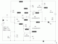
This is the "gain" block for the new filter I'm making, using reasonably non-exotic parts available from places like Digi-Key and Mouser. The Darlington stage fed back 100% to the input mosfet source helps limit the current excursion of the input device and pumps up linearity.
The part values shown would more or less work in real life, though one can take some liberties with the values for the input and output coupling caps, especially for the high pass section. I'm using 0.1uF Russian polystyrene caps for all the inputs, and for the high pass outputs. The output caps for the low pass section will be 3uF polypropylenes made by Aerovox. The frequency-determinimg caps are Roederstein KP1830 series polypropylene/foil, 1.5 nF, 100V. All the caps were obtained from Ebay/surplus sources.
The part values shown would more or less work in real life, though one can take some liberties with the values for the input and output coupling caps, especially for the high pass section. I'm using 0.1uF Russian polystyrene caps for all the inputs, and for the high pass outputs. The output caps for the low pass section will be 3uF polypropylenes made by Aerovox. The frequency-determinimg caps are Roederstein KP1830 series polypropylene/foil, 1.5 nF, 100V. All the caps were obtained from Ebay/surplus sources.
Attachments
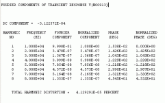
I had some residual hmmm with my first crossover circuit and power supply shown in posts 1 and 2. Construction and shielding seemed to be OK, and closing and screwing the box entirely shut had no effect. I used 4 X 1uF stacked film capacitors for bypass on the +30V rails of the filter. These serve for both local bypass for the filter modules and compensation for the regulator. I replaced these with 4 X 68 uF, 63V Panasonic FC series caps, and all is now silent. I suspect that the regulator may have been oscillating. Not all is seen in simulation-land, especially when you consider variables like circuit layout. The bypass caps are sprinkled around the board to provide both local bypass for the filter circuits and compensation for the regulator. Obviously 4uF and vanishingly small ESR did not make the grade in terms of stability. I may tack some extra film capacitors on the back of the board to provide some extra HF bypassing.
My next revision board (almost complete) is using a quite different (and much more slippery) regulation scheme. The filter circuits are all missing some important devices (en route), so now is the time to do some pulsed load testing to determine the actual regulator performance. Results will follow.
My next revision board (almost complete) is using a quite different (and much more slippery) regulation scheme. The filter circuits are all missing some important devices (en route), so now is the time to do some pulsed load testing to determine the actual regulator performance. Results will follow.
Last edited:
Hello wrenchone,
Hummm is evil and hard to kill. It shows up when you do not want it. Thanks for sharing real world details.
DT
All just for fun!
Hummm is evil and hard to kill. It shows up when you do not want it. Thanks for sharing real world details.
DT
All just for fun!
I wonder if the pages contained within here could be used to produce a jfet parametric EQ or simple 3 band filter for headphones? I like all different types, but they need to be dialed in to be 'ear flat' and I would love to be able to do that with a discrete circuit on the output of a discrete smd super regulated and diamond buffered unity gain balanced amp that i'm using on the output of my dac to drive my headphones directly. i'll be kee[ping an eye on this thread, I am also looking to build myself a new set of active monitors that this may help with.
oh BTW, have you had a look at the linear systems LSK170 and same in duals? they can be had for considerably less than the toshiba parts, but you must adapt for package differences as they are smd soic8 and ...TO-2 (not certain of the second one_
oh BTW, have you had a look at the linear systems LSK170 and same in duals? they can be had for considerably less than the toshiba parts, but you must adapt for package differences as they are smd soic8 and ...TO-2 (not certain of the second one_
I'm also wondering why not use the 2sk170? Every single piece of hi-fi I have has at least some of these in key gain stages.
Phono stage - 4x 2sk170
Shunt reg for phono stage - 6x 2sk170
Buffer - 4x 2sk170
Shunt reg for buffer - 6x 2sk170
Power Amp - 2x 2sk170 (& counterpart sj74 too)
They're not too expensive if you buy 50 at a time off eBay, and are exceptionally good.
Have a look at the datasheet: http://www.datasheetcatalog.com/datasheets_pdf/2/S/K/1/2SK170.shtml
Last edited:
You're perfectly free to use the 2SK170 if you feel so compelled. This thread proves you don't need to if you don't want to - and I don't. I save my 2SK170s for where I really need them - for example, the first stage of an RIAA amp. For MM inputs they aren't strictly necessary even then.
Last edited:
Expensive, hard/harder to get, not really needed for a high signal level application, knee-jerk response to other's knee-jerk response (oh, you need this yadayadayada part or you'll never get good results). I can get hundreds of PN4393s from Mouser at $0.35 apiece (I already have hundreds). This is a real plus if you're trying to really closely match parts. The PN4393 has a rather low input and reverse transfer capacitance. Also, the exponential break point for its gate current leakage characteristic is much higher than that of the 2SK170. It's a nice workhorse fet for many applications.
I do have a jfet RIAA design in the works that uses a cascoded 2SK170 front end. (BTW, the 2SK170 is cascoded using a PN4391, the higher IDSS cousin of the PN4393 - it's perfect for the job). However, the second stage is a PN4393/J176 feedback pair, yielding much lower distortion than the standard "Pacific" RIAA circuit that uses a simple 2SK170 common source amplifier in both positions.
I do have a jfet RIAA design in the works that uses a cascoded 2SK170 front end. (BTW, the 2SK170 is cascoded using a PN4391, the higher IDSS cousin of the PN4393 - it's perfect for the job). However, the second stage is a PN4393/J176 feedback pair, yielding much lower distortion than the standard "Pacific" RIAA circuit that uses a simple 2SK170 common source amplifier in both positions.
- Status
- Not open for further replies.
- Home
- Source & Line
- Analog Line Level
- JFET Active Crossover