Well, you know your fets. And you're right, it's totally knee jerk. It makes me want to understand your circuit better.
Good thread; this has come into interest for me since my MFB opamp with class-A bias capability plan fell through.
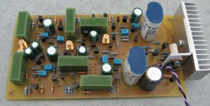
Interested to know if you built and tested this iteration, seems to me to be a good choice in terms of economy and performance. But one question about it is the noise in practice - supposedly MOSFETs are noisier, but how much, really?This is the "gain" block for the new filter I'm making, using reasonably non-exotic parts available from places like Digi-Key and Mouser. The Darlington stage fed back 100% to the input mosfet source helps limit the current excursion of the input device and pumps up linearity.
not that much, but they do tend to need higher current/voltage to get the performance out of them. Owen 'OPC' got 115db THD+noise measured performance from a DEEEEEP class A biased modified mosfet pass D1 IV on the output of a buffalo II. not sure if it applies in this application, but pumping the supply right up to +/- 55vdc got this performance as the transconductance went up exponentially with the supply voltage, this is very important for best performance from sabre, but maybe not so much here
Last edited:
The new filter is in the last stages of stuffing the board. I don't have a big concern about noise, as I'm running a similar circuit as a lineamp without any problems.
Here's a picture of the new board. It will go inside my new preamp chassis. I'm using SMA RF connectors for ins and outs, and have a central power distribution barrier strip so that I can easily swap functinal blocks. There will be three blocks living inside, all of a standardized size and mounting hole pattern - an RIAA preamp, a lineamp, and an active crossover. I need to get a few more SMA connctors to finish stuffing the board, then I can test.
Attachments
nice work; the SMA connectors are nice. i'm also using the AMC for i2s and low level signal transfer in my dac. and probably getting some QMA for my preamp (quick release SMA)
Well, I just put some components on order to produce some plug in veroboards to replace the opamps on my current board, though the space is pretty cramped.
I went with 5LN01N for the MOSFET and 2SA933AS for the BJT. I also put some 2SC1740S's on order for tests between BJT control elements and MOSFETs.
In the meantime when I wait for these components I could probably knock up a BJT version with A1015's and C1815's that I have lying around.
Also one thing I noticed whilst simulating is that even with very small currents running through the MOSFET (essentially BJT level currents) I can still obtain very good THD (~2.0e-6 %) simulations - I'm not sure if I'm missing something regarding how the MOSFET models can be used here. Also I was using the ROHM RUE003N02 model because I can't load the 5LN01 models into TINA-TI :/ I guess it's a hint that I should move to LTSpice.
Attachments
The new filter is in the last stages of stuffing the board. I don't have a big concern about noise, as I'm running a similar circuit as a lineamp without any problems.
Hello Wrenchone,
How did this work out? Did it get traction?
DT
All just for fun!
Board is done, connectors installed, and it is waiting to be put in a case with the rest of the modules (RIAA preamp and lineamp). I powered it up, and all the static voltage levels in strategic spots are just fine (a good sign).I just got some 50k "black block" Noble pots for the crossover level controls. All this is being time division multiplexed with life and several other projects.
Last edited:
Wrenchone,
I’ll be patient and put my coffee back in the microwave.
Thank you.
DT
All just for fun!
I’ll be patient and put my coffee back in the microwave.
Thank you.
DT
All just for fun!
Why wait for whatt I'm doing- roll your own.
Hello Wrenchone,
In a previous life I could roll em in the back seat of a VW bug in the dark.
I spent too much. I bought 1K 2SK170’s in factory packaging.
I am now building a Salas NJFET RIAA preamplifier. Sorting out part matching, power supplies and capacitor selection seems a bit more straight forward with fewer parts to juggle.
I have some Vifa drivers mounted as Linkwitz style dipoles. So far the dipoles are operating with digital crossovers. There is more refining of crossover points and such to do. I am planning to attend Burning Amp in October and listen to the real thing before getting too deep into the JFET active crossover and equalization.
DT
All just for fun!
Yes, Virginia, the crossover makes a difference.... It's not the first time I changed a speaker/crossover and hated my CD player afterwards. This time, it's partially the speaker's fault. I just finished a set of Tri Trix speakers from Parts Express's "Recession Buster" kit. Most of the frustration was finishing the MDF cabinets and figuring out how to do the ins and out for a bi-amped setup. I gave up trying to put lipstick on the pig (MDF cabinets) and used spray-on truck bed liner from Kragen.The result is a pair of speakers that are very black and very functional. They were sharp and shouty with a 5kHz crossover point, making my CD player sound very strident, and painful on crescendos. I looked up the curves on the drivers, and there's a big fat peak at 5kHz on the Dayton 5 1/4" mid-woofs. The crossover point for the passive crossovers designed for these speakers looks to be set to ~1.5kHz to take advantage of the extended tweeter response, and to knock down that peak. I took apart the jfet crossover today and reset things accordingly (30.9k resistors and 3n3 capacitors), and the speakers are quite different now, definitely less strident. I will chime in again after some more listening.
BTW -these observations are all using the first crossover circuit I posted using 2 X PN4393 employed in current source loaded source followers for each stage (2 follower stages for each filter element - input buffer, then actual filter). With a couple of value changes, J310s would probably work just as well (widely available on E-pay...). The second filter hasn't been aired yet - it's sitting patiently in the basement waiting to be fitted with a case and power supply..
Can you enlighten me with some info on pros and cons of this type of crossover vs the opamp type such as Rod Elliott espouses?
Read Calvin's comments near the beginning of this thread, as he's actually listened to both opamps and discrete circuits. I went into this project with no intention of using opamps whatsoever, as the power supply scheme/design philosophy of my preamp is based on the use of simple jfet and mosfet circuits. So far, I haven't been disappointed.
Hello,Can you enlighten me with some info on pros and cons of this type of crossover vs the opamp type such as Rod Elliott espouses?
Op-Amps have huge open loop gain and huge feedback. Pro and con sides of the same coin resulting in the life’s breathe being sucked out of the music and high Power Supply Rejection Ratio.
DT
All just for fun!
Hi
KJ, if You look at the application You´ll see that the gain demand is either unity or quite low. Now if You need a gain of 1 the easiest way to generate that is to use a emitter-, source-, or cathode follower. Such a circuit features a (local) feedback factor of 1 (i.e 100%). Its capabilities may be enhanced by current source loading instead of using a discrete resistor.
Now who in his right mind would add to this nice little circuit a couple of dozen of transistors to design a highly nonlinear multistage-circuit with tons of unneccessary gain, which requires tons of global feedback to smash all the excessive gain at the end to a value of 1??? Just because such a overkill of circuitry is pressed into a small plastic package and doesn´t cost much nowadays makes things any better. If You need lots of gain, as for example with phono stages, a OPamp can be just fine.
You might argue the OPamp´s distortion figures look better, but the typical THD-measurement with a single tone doesn´t correlate at all with sonic impressions, a fact known at least for the last 30years. It only offers a simple figure that tells the developer that his circuit works...no more no less. THD-figures don´t tell the listener anything, nothing, nope, nada, nein.
More elaborate multi-tone THD-measurements reveal that OP-Amp circuits (and most power amplifiers are built after this fashion) are quite often far from beeing good, even when single-tone THD-measurements look perfect. The more tones included in the signal the more obvious the results seem to correlate with sonic impressions. Sadly such measurements are non standard and the industry rather refuses to use non-standards, at least officially.
The HiFi-magazines still print those figures well knowing that apart from suggesting competence and knowledge there are only marketing reasons.
Unfortunately most readers are fooled to believe in these figures and don´t trust their ears or their tapping feet.
If they would, audio circuitry probabely would look a bit different in many cases. 🙄
jauu
Calvin
Calvin, thank you for your detailed reply to my question. Unfortunately I am completely new to all of this and am not able in the slightest to look at the application and understand much about it.
I am, however, looking to try some DIY projects and would need to know where something like a kit might be available.
I would even like to hear for myself and build one of Ron Elliott's active crossovers and one like wrenchone in order to do my own A/B blind comparisons. I don't think there's any chance of looking at wrenchone's diagram and creating one of these on my own.
Please don't take this in the wrong way, but I find it hard to understand why apparently none of the high-end-money-is-no-object products have adopted such a superior method of audio reproduction.
Anyway, I'm still very curious to hear what the fuss is all about. Without a lot of help, I don't think that will happen, however.
Regards,
Ken
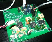
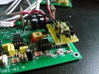
I don't really want to taint wrenchone's thread with my budget discrete efforts, but if you want to do comparisons you can simply do what I've done and build the op-amp version of the crossover and then make discrete plug-in buffers to compare.
Of course this only works for replacing non-inverting op-amp stages and you need to add DC blocking in some areas, but most of the ones on for example Rod Elliot's board are non-inverting (e.g all the filter stages and the output buffers - the input buffer could easily enough be noninverting if you didn't use his balanced input scheme)
P.S. This is what I ended up doing with my board on the last page - the 5LN01SP's turned out to be pretty good listening to them, though I have no measurements yet.
Attachments
- Status
- Not open for further replies.
- Home
- Source & Line
- Analog Line Level
- JFET Active Crossover